The Arduino extension fully embraces the Arduino developer community and is almost fully compatible and consistent with the official Arduino IDE. On top of it, we added the most sought-after features, such as IntelliSense, Auto code completion, and on-device debugging for supported boards.
Here is a list of the core functionalities:
IntelliSense and syntax highlighting for Arduino sketches
Verify and upload your sketches in Visual Studio Code
Built-in board and library manager
Built-in example list
Built-in serial monitor
Snippets for sketches
Automatic Arduino project scaffolding
Command Palette (F1) integration of frequently used commands (e.g. Verify, Upload…)
New Integrated Arduino Debugging
For Arduino extension users, you can directly download and install the extension from Visual Studio Code Marketplace at: https://aka.ms/arduino.
Last post show a simple program run on ESP8266/NodeMCU to read Analog Input and send to Serial. And display the data on Raspberry Pi 3 using Arduino IDE Serial Plotted. This post show a Python example run on Raspberry Pi 3/Raspbian Jessie with PIXEL, to plot the serial data graphically using matplotlib library.
pyserialplot.py
import numpy as np
import matplotlib as mpl
import matplotlib.pyplot as plt
import matplotlib.animation as animation
import serial
import platform

print("Python version: " + platform.python_version())
print("matplotlib version: " + mpl.__version__)

fig, ax = plt.subplots()
line, = ax.plot(np.random.rand(10))
ax.set_ylim(0, 1030)
xdata, ydata = [0]*100, [0]*100
SerialIn = serial.Serial("/dev/ttyUSB0",9600)

def update(data):
    line.set_ydata(data)
    return line,

def run(data):
    global xdata, ydata
    x,y = data
    if (x == 0):
        xdata = [0]*100
        ydata = [0]*100
    del xdata[0]
    del ydata[0]
    xdata.append(x)
    ydata.append(y)
    line.set_data(xdata, ydata)
    return line,

def data_gen():
    x = 9
    while True:
        if (x >= 9):
            x = 0
        else:
            x += 0.1

        try:
            inRaw = SerialIn.readline()
            inInt = int(inRaw)
        except:
            inInt = 0

        yield x, inInt

ani = animation.FuncAnimation(fig, run, data_gen, interval=0, blit=True)
plt.show()
This python example can be run on both Python 2 and 3. To run this on Raspberry Pi/Raspbian Jessie with PIXEL, matplotlib library is need.
For Python 2: $ sudo apt-get install python-matplotlib
For Python 3: $ sudo apt-get install python3-matplotlib
In the following code, we have to get the port connected. SerialIn = serial.Serial("/dev/ttyUSB0",9600)
In Raspberry Pi/Raspbian Jessie with PIXEL, it is /dev/ttyUSB0 normal. We can check it with: $ ls /dev/ttyUSB0*
Run on Ubuntu:
The Python script work on PC/Ubuntu also. This video show running on Ubuntu 17.04/Payton 3.6 (actually behind Windows 10/VirtualBox).
This example of ESP8266/NodeMCU read input from A0, and output to Serial. The receiving side is a Raspberry Pi 3 running Raspbian Jessie with PIXEL and Arduino IDE installed, the result is display graphically using Arduino IDE's Serial Plotter. All job done on Raspberry Pi 3. ESP8266/NodeMCU connect to the Raspberry Pi 3 with USB.
Add Additional Board Manager URL for ESP8266 board:
> File > Preference
> Add "http://arduino.esp8266.com/stable/package_esp8266com_index.json" in Additional Board Manager URLs.
Add ESP8266 board to Arduino IDE:
- Open Boards Manager in Arduino IDE
- Search "esp8266" or "NodeMCU", you will find "esp8266 by ESP8266 Community". Install it.
This video show how to, and run the Blink example on ESP8266/NodeMCU. The Raspberry Pi 3 connect to a 4" 800x480 HDMI IPS LCD Display, so it display in low resolution.
/*
 *  This sketch run on ESP32 with Arduino core for ESP32,
 *  demonstrates how to set up a simple HTTP-like server.
 *  The server will set a GPIO pins depending on the request,
 *  to control the brightness of RGB LED connected to:
 *    23 : BLUE
 *    22 : GREEN
 *    21 : RED
 *
 *    http://server_ip/rgb/rrggbb/
 *    where rr is the value set RED
 *    where gg is the value set GREEN
 *    where bb is the value set BLUE
 *    then terminate with '/'
 *  server_ip is the IP address of the ESP32, will be
 *  printed to Serial when the module is connected.
*/
#include <WiFi.h>

const char* ssid = "ssid";
const char* password = "password";
WiFiServer server(80);

#define MAX_LED_VALUE 99
// use first 3 channels of 16 channels (started from zero)
#define LEDC_CHANNEL_0_R  0
#define LEDC_CHANNEL_1_G  1
#define LEDC_CHANNEL_2_B  2

// use 13 bit precission for LEDC timer
#define LEDC_TIMER_13_BIT  13

// use 5000 Hz as a LEDC base frequency
#define LEDC_BASE_FREQ     5000

// LED PINs
#define LED_PIN_R   21
#define LED_PIN_G   22
#define LED_PIN_B   23

/*
Because Multiple libraries were found for "WiFi.h",
Arduino IDE will:
 Used: ...\Arduino\hardware\espressif\esp32\libraries\WiFi
 Not used: C:\Program Files (x86)\Arduino\libraries\WiFi

And exit with error:
'min' was not declared in this scope

So I have to program my own min()
 */
uint32_t min(uint32_t num1, uint32_t num2){
  if(num1 < num2){
    return num1;
  }else{
    return num2;
  }
}

// Arduino like analogWrite
// value has to be between 0 and valueMax
void ledcAnalogWrite(uint8_t channel, uint32_t value, uint32_t valueMax = MAX_LED_VALUE) {
  // calculate duty
  uint32_t duty = (LEDC_BASE_FREQ / valueMax) * min(value, valueMax);

  // write duty to LEDC
  ledcWrite(channel, duty);
}

void setup() {
  Serial.begin(115200);
  delay(10);

  // Setup timer and attach timer to a led pins
  ledcSetup(LEDC_CHANNEL_0_R, LEDC_BASE_FREQ, LEDC_TIMER_13_BIT);
  ledcAttachPin(LED_PIN_R, LEDC_CHANNEL_0_R);
  ledcSetup(LEDC_CHANNEL_1_G, LEDC_BASE_FREQ, LEDC_TIMER_13_BIT);
  ledcAttachPin(LED_PIN_G, LEDC_CHANNEL_1_G);
  ledcSetup(LEDC_CHANNEL_2_B, LEDC_BASE_FREQ, LEDC_TIMER_13_BIT);
  ledcAttachPin(LED_PIN_B, LEDC_CHANNEL_2_B);

  // Connect to WiFi network
  Serial.println();
  Serial.println();
  Serial.print("Connecting to ");
  Serial.println(ssid);

  WiFi.begin(ssid, password);

  while (WiFi.status() != WL_CONNECTED) {
    delay(500);
    Serial.print(".");
  }
  Serial.println("");
  Serial.println("WiFi connected");

  // Start the server
  server.begin();
  Serial.println("Server started");

  // Print the IP address
  Serial.println(WiFi.localIP());
}

void loop() {
  // Check if a client has connected
  WiFiClient client = server.available();
  if (!client) {
    return;
  }

  // Wait until the client sends some data
  Serial.println("new client");
  while(!client.available()){
    delay(1);
  }

  // Read the first line of the request
  String req = client.readStringUntil('\r');
  Serial.println(req);
  client.flush();

  // Match the request
  int valR, valG, valB;
  String subStringR, subStringG, subStringB;
  int index = req.indexOf("/rgb/");
  if(index != -1){
    if(req.charAt(index+11)=='/'){
      subStringR = req.substring(index+5, index+7);
      subStringG = req.substring(index+7, index+9);
      subStringB = req.substring(index+9, index+11);
      Serial.println("R: " + subStringR);
      Serial.println("G: " + subStringG);
      Serial.println("B: " + subStringB);

      valR = subStringR.toInt();
      valG = subStringG.toInt();
      valB = subStringB.toInt();
      Serial.println("valR: " + String(valR));
      Serial.println("valG: " + String(valG));
      Serial.println("valB: " + String(valB));

    }
    else{
      Serial.println("Not terminated with /");
      client.stop();
      return;
    }
  }
  else {
    Serial.println("No /rgb/ found");
    client.stop();
    return;
  }

  // Set GPIOs according to the request
  // No check valid of the requested setting
  ledcAnalogWrite(LEDC_CHANNEL_0_R, valR);
  ledcAnalogWrite(LEDC_CHANNEL_1_G, valG);
  ledcAnalogWrite(LEDC_CHANNEL_2_B, valB);

  client.flush();

  // Prepare the response
  String s = "HTTP/1.1 200 OK\r\nContent-Type: text/html\r\n\r\n<!DOCTYPE HTML>\r\n<html>\r\nGPIOs of RGB is now ";
  s += String(valR) +":" + String(valG) + ":" + String(valB);
  s += "</html>\n";

  // Send the response to the client
  client.print(s);
  delay(1);
  Serial.println("Client disonnected");

  // The client will actually be disconnected
  // when the function returns and 'client' object is detroyed
}
This video show how to download, install and run Arduino IDE Linux ARM version (1 JUNE 2017 release), on Raspberry Pi 3 with Raspbian Jessie with PIXEL (2017-04-10 release). The Raspberry Pi connect to a 4" 800x480 HDMI IPS LCD Display, so it display in low resolution.
(All steps run on Raspberry Pi, remotely via VNC Viewer)
- Visit Arduino Software page. Scroll download to HOURLY BUILDS section, click to download Linux ARM version. It's release 1 JUNE 2017 currently.
- Extract the downloaded file.
- Change to the extracted directory.
- Run the install shell script. $ sudo ./install.sh
- A short-cut will be added in MENU -> Programming -> Arduino IDE
You can also update library and board in the installed Arduino IDE.
Test with a simple program to read/write between Raspberry Pi and Arduino via Serial/USB.
testUsb.ino
int byteIn;

void setup() {
  Serial.begin(9600);
  // initialize digital pin LED_BUILTIN as an output.
  pinMode(LED_BUILTIN, OUTPUT);
  Serial.print("Program started\n");
}

// the loop function runs over and over again forever
void loop() {
  if(Serial.available() > 0){
    byteIn = Serial.read();
    if(byteIn == '0'){
      digitalWrite(LED_BUILTIN, LOW);
      Serial.print("LED OFF\n");
    }else if(byteIn == '1'){
      digitalWrite(LED_BUILTIN, HIGH);
      Serial.print("LED ON\n");
    }else{
      Serial.print("unknown!\n");
    }
  }
}
For ESP-32 Wifi/Bluetooth module with Arduino core for ESP32, to output PWM to GPIO, we can call ledcWrite(), something like Arduino analogWrite() function.
It's a example to output PWM to GPIO 21, 22 and 23, to control color/brightness of RGB LED.
/*
 Arduino core for ESP32 example: output PWM to GPIO using ledcWrite()
 Modify from the example code:
 /ESP32/examples/AnalogOut/LEDCSoftwareFade
*/

// use first 3 channels of 16 channels (started from zero)
#define LEDC_CHANNEL_0_R  0
#define LEDC_CHANNEL_1_G  1
#define LEDC_CHANNEL_2_B  2

// use 13 bit precission for LEDC timer
#define LEDC_TIMER_13_BIT  13

// use 5000 Hz as a LEDC base frequency
#define LEDC_BASE_FREQ     5000

// LED PINs
#define LED_PIN_R   21
#define LED_PIN_G   22
#define LED_PIN_B   23

// Arduino like analogWrite
// value has to be between 0 and valueMax
void ledcAnalogWrite(uint8_t channel, uint32_t value, uint32_t valueMax = 255) {
  // calculate duty
  uint32_t duty = (LEDC_BASE_FREQ / valueMax) * min(value, valueMax);

  // write duty to LEDC
  ledcWrite(channel, duty);
}

void setup() {
  // Setup timer and attach timer to a led pins
  ledcSetup(LEDC_CHANNEL_0_R, LEDC_BASE_FREQ, LEDC_TIMER_13_BIT);
  ledcAttachPin(LED_PIN_R, LEDC_CHANNEL_0_R);
  ledcSetup(LEDC_CHANNEL_1_G, LEDC_BASE_FREQ, LEDC_TIMER_13_BIT);
  ledcAttachPin(LED_PIN_G, LEDC_CHANNEL_1_G);
  ledcSetup(LEDC_CHANNEL_2_B, LEDC_BASE_FREQ, LEDC_TIMER_13_BIT);
  ledcAttachPin(LED_PIN_B, LEDC_CHANNEL_2_B);
}

void loop() {
  ledcAnalogWrite(LEDC_CHANNEL_0_R, 0);
  ledcAnalogWrite(LEDC_CHANNEL_1_G, 0);
  ledcAnalogWrite(LEDC_CHANNEL_2_B, 0);
  delay(1000);

  for(int i = 0; i < 255; i++){
    ledcAnalogWrite(LEDC_CHANNEL_0_R, i);
    delay(10);
  }
  for(int i = 255; i > 0; i--){
    ledcAnalogWrite(LEDC_CHANNEL_0_R, i);
    delay(10);
  }

  for(int i = 0; i < 255; i++){
    ledcAnalogWrite(LEDC_CHANNEL_1_G, i);
    delay(10);
  }
  for(int i = 255; i > 0; i--){
    ledcAnalogWrite(LEDC_CHANNEL_1_G, i);
    delay(10);
  }

  for(int i = 0; i < 255; i++){
    ledcAnalogWrite(LEDC_CHANNEL_2_B, i);
    delay(10);
  }
  for(int i = 255; i > 0; i--){
    ledcAnalogWrite(LEDC_CHANNEL_2_B, i);
    delay(10);
  }

  for(int i = 0; i < 255; i++){
    ledcAnalogWrite(LEDC_CHANNEL_0_R, i);
    ledcAnalogWrite(LEDC_CHANNEL_1_G, i);
    ledcAnalogWrite(LEDC_CHANNEL_2_B, i);
    delay(10);
  }
  for(int i = 255; i > 0; i--){
    ledcAnalogWrite(LEDC_CHANNEL_0_R, i);
    ledcAnalogWrite(LEDC_CHANNEL_1_G, i);
    ledcAnalogWrite(LEDC_CHANNEL_2_B, i);
    delay(10);
  }
}
Connection:
Reference:
Example at /ESP32/examples/AnalogOut/LEDCSoftwareFade
or here.
It's another example to setup a simple HTTP-like server, to receive request from client, output PWM, to control color/brightness of RGB LED.
NodeMCU_WiFiWebServer_RGB.ino
/*
 *  This sketch run on NodeMCU (ESP8266),
 *  demonstrates how to set up a simple HTTP-like server.
 *  The server will set a GPIO pins depending on the request,
 *  to control the brightness of RGB LED connected to:
 *    D0 : BLUE
 *    D1 : GREEN
 *    D2 : RED
 *
 *    http://server_ip/rgb/rrggbb/
 *    where rr is the value set RED
 *    where gg is the value set GREEN
 *    where bb is the value set BLUE
 *    then terminate with '/'
 *  server_ip is the IP address of the NodeMCU, will be
 *  printed to Serial when the module is connected.
 */

#include <ESP8266WiFi.h>

const char* ssid = "Xtation";
const char* password = "password";

int ledB = D0;
int ledG = D1;
int ledR = D2;

// Create an instance of the server
// specify the port to listen on as an argument
WiFiServer server(80);

void setup() {
  Serial.begin(115200);
  delay(10);

  // prepare GPIOs for RGB LED
  pinMode(D0, OUTPUT);
  pinMode(D1, OUTPUT);
  pinMode(D2, OUTPUT);
  analogWriteRange(99); //PWM: 0~99

  // Connect to WiFi network
  Serial.println();
  Serial.println();
  Serial.print("Connecting to ");
  Serial.println(ssid);

  WiFi.begin(ssid, password);

  while (WiFi.status() != WL_CONNECTED) {
    delay(500);
    Serial.print(".");
  }
  Serial.println("");
  Serial.println("WiFi connected");

  // Start the server
  server.begin();
  Serial.println("Server started");

  // Print the IP address
  Serial.println(WiFi.localIP());
}

void loop() {
  // Check if a client has connected
  WiFiClient client = server.available();
  if (!client) {
    return;
  }

  // Wait until the client sends some data
  Serial.println("new client");
  while(!client.available()){
    delay(1);
  }

  // Read the first line of the request
  String req = client.readStringUntil('\r');
  Serial.println(req);
  client.flush();

  // Match the request
  int valR, valG, valB;
  String subStringR, subStringG, subStringB;
  int index = req.indexOf("/rgb/");
  if(index != -1){
    if(req.charAt(index+11)=='/'){
      subStringR = req.substring(index+5, index+7);
      subStringG = req.substring(index+7, index+9);
      subStringB = req.substring(index+9, index+11);
      Serial.println("R: " + subStringR);
      Serial.println("G: " + subStringG);
      Serial.println("B: " + subStringB);

      valR = subStringR.toInt();
      valG = subStringG.toInt();
      valB = subStringB.toInt();
      Serial.println("valR: " + String(valR));
      Serial.println("valG: " + String(valG));
      Serial.println("valB: " + String(valB));

    }
    else{
      Serial.println("Not terminated with /");
      client.stop();
      return;
    }
  }
  else {
    Serial.println("No /rgb/ found");
    client.stop();
    return;
  }

  // Set GPIOs according to the request
  // No check valid of the requested setting
  analogWrite(ledR, valR);
  analogWrite(ledG, valG);
  analogWrite(ledB, valB);

  client.flush();

  // Prepare the response
  String s = "HTTP/1.1 200 OK\r\nContent-Type: text/html\r\n\r\n<!DOCTYPE HTML>\r\n<html>\r\nGPIOs of RGB is now ";
  s += String(valR) +":" + String(valG) + ":" + String(valB);
  s += "</html>\n";

  // Send the response to the client
  client.print(s);
  delay(1);
  Serial.println("Client disonnected");

  // The client will actually be disconnected
  // when the function returns and 'client' object is detroyed
}
Example of NodeMCU with ESP8266 Arduino Core to output PWM by calling analogWrite(), to control brightness of RGB LED.
NodeMCU_PWM.inf
int ledB = D0;
int ledG = D1;
int ledR = D2;

void setup() {
  pinMode(D0, OUTPUT);
  pinMode(D1, OUTPUT);
  pinMode(D2, OUTPUT);
  //Set PWM frequency 500, default is 1000
  //Set range 0~100, default is 0~1023
  analogWriteFreq(500);
  analogWriteRange(100);
}

// the loop function runs over and over again forever
void loop() {
  analogWrite(ledR, 0);
  analogWrite(ledG, 0);
  analogWrite(ledB, 0);
  delay(500);
  analogWrite(ledR, 100);
  analogWrite(ledG, 100);
  analogWrite(ledB, 100);
  delay(500);
  analogWrite(ledR, 0);
  analogWrite(ledG, 0);
  analogWrite(ledB, 0);
  delay(500);

  int i;
  for(i=0; i<100; i++){
    analogWrite(ledR, i);
    delay(10);
  }
  analogWrite(ledR, 0);

  for(i=0; i<100; i++){
    analogWrite(ledG, i);
    delay(10);
  }
  analogWrite(ledG, 0);

  for(i=0; i<100; i++){
    analogWrite(ledB, i);
    delay(10);
  }
  analogWrite(ledB, 0);

  for(i=0; i<100; i++8){
    analogWrite(ledR, i);
    analogWrite(ledG, i);
    analogWrite(ledB, i);
    delay(10);
  }

  for(i=100; i>0; i--){
    analogWrite(ledR, i);
    analogWrite(ledG, i);
    analogWrite(ledB, i);
    delay(10);
  }

}
Reference: analogWrite(pin, value) enables software PWM on the given pin. PWM may be used on pins 0 to 16. Call analogWrite(pin, 0) to disable PWM on the pin. value may be in range from 0 to PWMRANGE, which is equal to 1023 by default. PWM range may be changed by calling analogWriteRange(new_range).
PWM frequency is 1kHz by default. Call analogWriteFreq(new_frequency) to change the frequency.
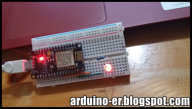
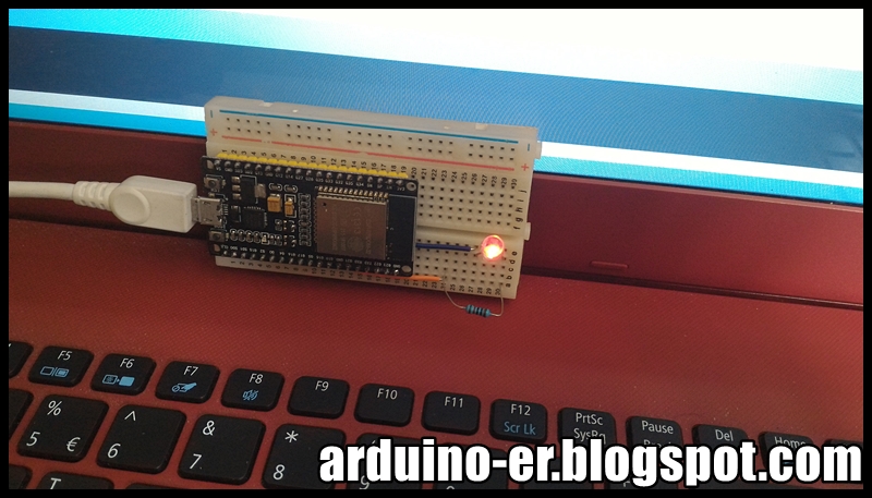
This example show how to read input (D5, D6 & D7) from buttons, and write output (D0, D1 & D2) to LEDs accordingly. For the input, all set INPUT_PULLUP to enable internal pull-up resistor, so no external resistors needed.
Connection:
/*
NodeMCU IO index vs ESP8266 pin
IO index  ESP8266 pin
    0     [*] GPIO16
    1     GPIO5
    2     GPIO4
    3     GPIO0
    4     GPIO2
    5     GPIO14
    6     GPIO12
    7     GPIO13
    8     GPIO15
    9     GPIO3
    10    GPIO1
    11    GPIO9
    12    GPIO10
[*] D0(GPIO16) can only be used as gpio read/write.
No support for open-drain/interrupt/pwm/i2c/ow.
https://nodemcu.readthedocs.io/en/master/en/modules/gpio/
 */

void setup() {
  pinMode(D0, OUTPUT);
  pinMode(D1, OUTPUT);
  pinMode(D2, OUTPUT);
  pinMode(D5, INPUT_PULLUP);
  pinMode(D6, INPUT_PULLUP);
  pinMode(D7, INPUT_PULLUP);
}

// the loop function runs over and over again forever
void loop() {
  if(digitalRead(D5)){
    digitalWrite(D0, LOW);
  }else{
    digitalWrite(D0, HIGH);
  }

  if(digitalRead(D6)){
    digitalWrite(D1, LOW);
  }else{
    digitalWrite(D1, HIGH);
  }

  if(digitalRead(D7)){
    digitalWrite(D2, LOW);
  }else{
    digitalWrite(D2, HIGH);
  }

}
Usage of GPIO:
At the beginning, I want to use D6, D7 and D8 as input. But D8 always return LOW. After googled and found schematic diagram of NodeMCU DevKit v1.0 here: https://github.com/nodemcu/nodemcu-devkit-v1.0/blob/master/NODEMCU_DEVKIT_V1.0.PDF. It's found that GPIO15 (D8) connect to GND via a resistor, so always return LOW.
And MATTERS NEEDING ATTENTION can be found in the schematic diagram: On every boot/reset/wakeup, GPIO15 MUST keep LOW, GPIO2 MUST keep HIGH. GPIO0 HIGH -> RUN MODE, LOW -> FLASH MODE. When you need to use the sleep mode, GPIO16 and RST should be connected, and GPIO16 will output LOW to reset the system at the time of wakeup.
There are many version of ESP8266, the printed mark on PCB may not the io number of ESP8266 MCU, you have to check it for your board. This example run on NodeMCU with marking and CPU pin assignment:
NodeMCU IO index vs ESP8266 pin
IO index  ESP8266 pin
    0     [*] GPIO16
    1     GPIO5
    2     GPIO4
    3     GPIO0
    4     GPIO2
    5     GPIO14
    6     GPIO12
    7     GPIO13
    8     GPIO15
    9     GPIO3
    10    GPIO1
    11    GPIO9
    12    GPIO10
[*] D0(GPIO16) can only be used as gpio read/write.
No support for open-drain/interrupt/pwm/i2c/ow.
https://nodemcu.readthedocs.io/en/master/en/modules/gpio/
If you run on NodeMCU and select board of NodeMCU 1.0, you can use D1~D10 to access the pins. Refer to pins_arduino.h. Both D1 and 5 refer to the same pin.
If you run on other module, and select other board, may be the compile will report error of 'D1' was not declared in this scope. You have to specify the io# of the MCU, 5 in this case.
NodeMCU_Blink.ino
/*
NodeMCU IO index vs ESP8266 pin
IO index  ESP8266 pin
    0     [*] GPIO16
    1     GPIO5
    2     GPIO4
    3     GPIO0
    4     GPIO2
    5     GPIO14
    6     GPIO12
    7     GPIO13
    8     GPIO15
    9     GPIO3
    10    GPIO1
    11    GPIO9
    12    GPIO10
[*] D0(GPIO16) can only be used as gpio read/write.
No support for open-drain/interrupt/pwm/i2c/ow.
https://nodemcu.readthedocs.io/en/master/en/modules/gpio/
 */

/*
 * For NodeMCU (8266) both D1 and 5 refer to the same pin
 * For others, such as "Generic ESP8266 Module", it will
 * report error of: 'D1' was not declared in this scope.
 */
const int io5 = 5;

// the setup function runs once when you press reset or power the board
void setup() {
  // initialize digital pins as an output.
  pinMode(LED_BUILTIN, OUTPUT);
  //pinMode(D1, OUTPUT);
  pinMode(io5, OUTPUT);
}

// the loop function runs over and over again forever
void loop() {
  digitalWrite(LED_BUILTIN, HIGH);
  //digitalWrite(D1, HIGH);
  digitalWrite(io5, HIGH);
  delay(500);
  //digitalWrite(D1, LOW);
  digitalWrite(io5, LOW);
  delay(500);
  digitalWrite(LED_BUILTIN, LOW);
  //digitalWrite(D1, HIGH);
  digitalWrite(io5, HIGH);
  delay(500);
  //digitalWrite(D1, LOW);
  digitalWrite(io5, LOW);
  delay(500);
}
What you have to do is change the ssid, password and the io number of the LED.
SimpleWiFiServer.ino
/*
  WiFi Web Server LED Blink

 A simple web server that lets you blink an LED via the web.
 This sketch will print the IP address of your WiFi Shield (once connected)
 to the Serial monitor. From there, you can open that address in a web browser
 to turn on and off the LED on pin 21.

 If the IP address of your shield is yourAddress:
 http://yourAddress/H turns the LED on
 http://yourAddress/L turns it off

 This example is written for a network using WPA encryption. For
 WEP or WPA, change the Wifi.begin() call accordingly.

 Circuit:
 * WiFi shield attached
 * LED attached to pin 21

 created for arduino 221 Nov 2012
 by Tom Igoe

ported for sparkfun esp32
31.01.2017 by Jan Hendrik Berlin

 */

#include <WiFi.h>

const char* ssid     = "ssid";
const char* password = "password";

WiFiServer server(80);

void setup()
{
    Serial.begin(115200);
    pinMode(21, OUTPUT);      // set the LED pin mode

    delay(10);

    // We start by connecting to a WiFi network

    Serial.println();
    Serial.println();
    Serial.print("Connecting to ");
    Serial.println(ssid);

    WiFi.begin(ssid, password);

    while (WiFi.status() != WL_CONNECTED) {
        delay(2100);
        Serial.print(".");
    }

    Serial.println("");
    Serial.println("WiFi connected");
    Serial.println("IP address: ");
    Serial.println(WiFi.localIP());

    server.begin();

}

int value = 0;

void loop(){
 WiFiClient client = server.available();   // listen for incoming clients

  if (client) {                             // if you get a client,
    Serial.println("new client");           // print a message out the serial port
    String currentLine = "";                // make a String to hold incoming data from the client
    while (client.connected()) {            // loop while the client's connected
      if (client.available()) {             // if there's bytes to read from the client,
        char c = client.read();             // read a byte, then
        Serial.write(c);                    // print it out the serial monitor
        if (c == '\n') {                    // if the byte is a newline character

          // if the current line is blank, you got two newline characters in a row.
          // that's the end of the client HTTP request, so send a response:
          if (currentLine.length() == 0) {
            // HTTP headers always start with a response code (e.g. HTTP/1.1 200 OK)
            // and a content-type so the client knows what's coming, then a blank line:
            client.println("HTTP/1.1 200 OK");
            client.println("Content-type:text/html");
            client.println();

            // the content of the HTTP response follows the header:
            client.print("Click <a href=\"/H\">here</a> turn the LED on pin 21 on<br>");
            client.print("Click <a href=\"/L\">here</a> turn the LED on pin 21 off<br>");

            // The HTTP response ends with another blank line:
            client.println();
            // break out of the while loop:
            break;
          } else {    // if you got a newline, then clear currentLine:
            currentLine = "";
          }
        } else if (c != '\r') {  // if you got anything else but a carriage return character,
          currentLine += c;      // add it to the end of the currentLine
        }

        // Check to see if the client request was "GET /H" or "GET /L":
        if (currentLine.endsWith("GET /H")) {
          digitalWrite(21, HIGH);               // GET /H turns the LED on
        }
        if (currentLine.endsWith("GET /L")) {
          digitalWrite(21, LOW);                // GET /L turns the LED off
        }
      }
    }
    // close the connection:
    client.stop();
    Serial.println("client disonnected");
  }
}
int LED = 21;

// the setup function runs once when you press reset or power the board
void setup() {
  // initialize digital pin LED_BUILTIN as an output.
  pinMode(LED, OUTPUT);
}

// the loop function runs over and over again forever
void loop() {
  digitalWrite(LED, HIGH);   // turn the LED on (HIGH is the voltage level)
  delay(100);                       // wait for a second
  digitalWrite(LED, LOW);    // turn the LED off by making the voltage LOW
  delay(100);                       // wait for a second
}
This example show how to get the WiFi MAC address of ESP32 Module, using
Arduino core for ESP32. In this example, I just want to know the MAC address only, without connect to
any hotspot, so no ssid and password needed (or it will connect to last
ssid).
ESP32_WiFi.ino
/*
 * ESP-32 Example,
 * start WiFi (without ssid and password)
 * and print the MAC address to Serial.
 * http://arduino-er.blogspot.com/
 */

#include <WiFi.h>

byte mac[6];

void setup()
{
    Serial.begin(115200);
    delay(1000);

    Serial.println();
    Serial.print("Program Start...");

    WiFi.begin();
    Serial.println("WiFi began");
    WiFi.macAddress(mac);

    Serial.print("MAC: ");
    Serial.print(mac[0],HEX);
    Serial.print(":");
    Serial.print(mac[1],HEX);
    Serial.print(":");
    Serial.print(mac[2],HEX);
    Serial.print(":");
    Serial.print(mac[3],HEX);
    Serial.print(":");
    Serial.print(mac[4],HEX);
    Serial.print(":");
    Serial.println(mac[5],HEX);

}

void loop(){

}
It match with the scanned address of the wireless router.
Remark:
May be it's something wrong on my ESP32 board; sometimes the program halt on the
code WiFi.begin() without return. Try to close Serial Monitor, disconnect and
reconnect ESP32 USB cable, then run Serial Monitor.
added@2022-03-12
Get MAC address of available WiFi network
It's a WiFiScan example installed with arduino-esp32. It act
as WIFI_STA, scan available WiFi network and print the SSID, RSSI...
To get the mac address, call BSSID(), return uint8_t *. Or call BSSIDstr(),
return String. Basically, BSSID is its MAC address.
/*
 *  This sketch demonstrates how to scan WiFi networks.
 *  The API is almost the same as with the WiFi Shield library,
 *  the most obvious difference being the different file you need to include:
 */
#include "WiFi.h"

void setup()
{
    Serial.begin(115200);

    // Set WiFi to station mode and disconnect from an AP if it was previously connected
    WiFi.mode(WIFI_STA);
    WiFi.disconnect();
    delay(100);

    Serial.println("Setup done");
}

void loop()
{
    Serial.println("scan start");

    // WiFi.scanNetworks will return the number of networks found
    int n = WiFi.scanNetworks();
    Serial.println("scan done");
    if (n == 0) {
        Serial.println("no networks found");
    } else {
        Serial.print(n);
        Serial.println(" networks found");
        for (int i = 0; i < n; ++i) {
            // Print SSID and RSSI for each network found
            Serial.print(i + 1);
            Serial.print(": ");
            Serial.print(WiFi.SSID(i));
            Serial.print(" (");
            Serial.print(WiFi.RSSI(i));
            Serial.print(")");
            Serial.println((WiFi.encryptionType(i) == WIFI_AUTH_OPEN)?" ":"*");

            //get MAC address
            uint8_t * nBSSID = WiFi.BSSID(i);
            Serial.println(WiFi.BSSIDstr(i)); //BSSIDstr() return in String

            delay(10);
        }
    }
    Serial.println("");

    // Wait a bit before scanning again
    delay(5000);
}
The video show how to install Arduino core for ESP32 to Arduino IDE, on Windows 10. Basically it follow the Installation Instructions for Windows, except the Target Directory.
It's assumed you have already installed Arduino IDE, Git and suitable USB driver for your ESP32 dev board.
The MKRFOX1200 is a powerful board that combines the functionality of the Zero and Sigfox connectivity. It is the ideal solution for Makers looking to design IoT projects with minimal previous experience in networking.
ESP32 is a low-cost, low-power system on a chip (SoC) series with Wi-Fi & dual-mode Bluetooth capabilities! The ESP32 series of chips presently includes ESP32-D0WDQ6 (and ESP32-D0WD), ESP32-D2WD, and ESP32-S0WD. At its heart, there's a dual-core (or single-core) Tensilica Xtensa LX6 microprocessor with a clock rate of up to 240 MHz. ESP32 is highly integrated with built-in antenna switches, RF balun, power amplifier, low-noise receive amplifier, filters, and power management modules. Engineered for mobile devices, wearable electronics, and IoT applications, ESP32 achieves ultra-low power consumption through power saving features including fine resolution clock gating, multiple power modes, and dynamic power scaling. ~ know more: http://esp32.net/
My first try Arduino Web Editor/Arduino 101 with Gyro example. Assume Arduino plug-ins was installed correctly, and Arduino 101 is connect to PC.
The Arduino Web Editor allows you to write code and upload sketches to any official Arduino and Genuino board from your web browser (Chrome, Firefox, Safari and Edge) after installing a plugin (repository available here).