Part I: Row Anode Column Cathode 8x8 LED Matrix, 1588BS as example. Current flow from pin 1 to pin 16 to make LED on row 5 col 8 ON.
Use the example of Row-Column Scanning an 8x8 LED matrix to show it work.
The connection between Arduino Uno and 8x8 LED Matrix is show here:
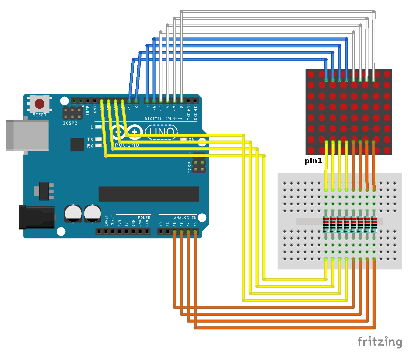
(It's recommended to add 220 ohm resisters to limit the current)
We need a test program to verify our connection, visit http://goo.gl/tXySxV, copy the example sketch of Walking bit on 8*8 LED Matrix, and download to Arduino Uno.
If your 8x8 LED Matrix have no marking for pin 1, we can use a multimeter to identify pin 1, and also pin 16.
This scheme diagram show when we apply +ve on pin 1 and -ve on pin 16, the LED on row 5 col 8 will be turn on.

Switch multimeter to diode test, the red lead will be +ve and black lead will be -ve.
Refer to the below video:
There are 4 possibility of pin 1 and 16, only one case will turn on a LED. When the LED (row 5 col 8) on, the pin connected to the RED lead of multimeter is pin 1.
Part II: Row Cathode Column Anode 8x8 LED Matrix, 1088AS as example. Current flow from pin 16 to pin 1 to make LED on row 5 col 8 ON.

Same procedure as in part I, with pin 1 on BLACK lead of multimeter.
Working example, refer to next post "Arduino Uno + SPI 8x8 LED Matrix, with MAX7219 LED driver".

where is the cod ?
ReplyDelete/*
Delete* Modify from Row-Column Scanning an 8x8 LED matrix tutorial
* http://arduino-er.blogspot.com/
*/
/*
Row-Column Scanning an 8x8 LED matrix with X-Y input
This example controls an 8x8 LED matrix using two analog inputs
created 27 May 2009
modified 30 Aug 2011
by Tom Igoe
This example works for the Lumex LDM-24488NI Matrix. See
http://sigma.octopart.com/140413/datasheet/Lumex-LDM-24488NI.pdf
for the pin connections
For other LED cathode column matrixes, you should only need to change
the pin numbers in the row[] and column[] arrays
rows are the anodes
cols are the cathodes
---------
Pin numbers:
Matrix:
* Digital pins 2 through 13,
* analog pins 2 through 5 used as digital 16 through 19
Potentiometers:
* center pins are attached to analog pins 0 and 1, respectively
* side pins attached to +5V and ground, respectively.
This example code is in the public domain.
http://www.arduino.cc/en/Tutorial/RowColumnScanning
see also http://www.tigoe.net/pcomp/code/category/arduinowiring/514 for more
*/
// 2-dimensional array of row pin numbers:
const int row[8] = {
2, 7, 19, 5, 13, 18, 12, 16
};
// 2-dimensional array of column pin numbers:
const int col[8] = {
6, 11, 10, 3, 17, 4, 8, 9
};
// 2-dimensional array of pixels:
int pixels[8][8];
int posX = 7;
int posY = 7;
int count = 30;
bool bg = false;
void setup() {
// initialize the I/O pins as outputs
// iterate over the pins:
for (int thisPin = 0; thisPin < 8; thisPin++) {
// initialize the output pins:
pinMode(col[thisPin], OUTPUT);
pinMode(row[thisPin], OUTPUT);
// take the col pins (i.e. the cathodes) high to ensure that
// the LEDS are off:
digitalWrite(col[thisPin], HIGH);
}
setupScreen();
}
void loop() {
// draw the screen:
refreshScreen();
if(count-- == 0){
count = 500;
if(posX--==0){
posX = 7;
if(posY--==0){
posY = 7;
bg = !bg;
}
}
setupScreen();
}
}
void setupScreen(){
if(bg){
//ON all others
for (int x = 0; x < 8; x++) {
for (int y = 0; y < 8; y++) {
pixels[x][y] = LOW;
}
}
//OFF current pos
pixels[posX][posY] = HIGH;
}else{
//OFF all others
for (int x = 0; x < 8; x++) {
for (int y = 0; y < 8; y++) {
pixels[x][y] = HIGH;
}
}
//ON current pos
pixels[posX][posY] = LOW;
}
}
void refreshScreen() {
// iterate over the rows (anodes):
for (int thisRow = 0; thisRow < 8; thisRow++) {
// take the row pin (anode) high:
digitalWrite(row[thisRow], HIGH);
// iterate over the cols (cathodes):
for (int thisCol = 0; thisCol < 8; thisCol++) {
// get the state of the current pixel;
int thisPixel = pixels[thisRow][thisCol];
// when the row is HIGH and the col is LOW,
// the LED where they meet turns on:
digitalWrite(col[thisCol], thisPixel);
// turn the pixel off:
if (thisPixel == LOW) {
digitalWrite(col[thisCol], HIGH);
}
}
// take the row pin low to turn off the whole row:
digitalWrite(row[thisRow], LOW);
}
}