
Sunday, July 17, 2016
Wednesday, June 29, 2016
Test nRF8001 Bluetooth LE module with nRF Master Control Panel (BLE) App on Android phone

This post show how to test Adafruit nRF8001 Bluetooth LE module with nRF Master Control Panel (BLE) App on Android phone.
- First of all, we have to install Adafruit nRF8001 library to Arduino IDE and connect Arduino Uno with nRF8001 module. Refer last post "Adafruit nRF8001 Bluetooth LE".


- Install "nRF Master Control Panel (BLE)" app on Android phone.
- Open echoDemo example provided in Adafruit nRF8001 library:
Examples > Adafruit nRF8001 echoDemo
Run on Uno and test with nRF Master Control Panel (BLE) App on Android phone, refer to the video:
Monday, June 27, 2016
Adafruit nRF8001 Bluetooth LE


Adafruit nRF8001 library for Arduino

adafruit/Adafruit_nRF8001 is driver and example code for Adafruit's nRF8001 Bluetooth Low Energy Breakout.
PINOUT

The pin locations are defined in ble_system.h, the supported systems are defined in hal_aci_tl.cpp. The following pinout is used by default for the Arduino Uno:
SCK -> Pin 13
MISO -> Pin 12
MOSI -> Pin 11
REQ -> Pin 10
RDY -> Pin 2 (HW interrupt)
ACT -> Not connected
RST -> Pin 9
3V0 - > Not connected
GND -> GND
VIN -> 5V
RDY must be on pin 2 since this pin requires a HW interrupt.
3V0 is an optional pin that exposes the output of the on-board 3.3V regulator. You can use this to supply 3.3V to other peripherals, but normally it will be left unconnected.
ACT is not currently used in any of the existing examples, and can be left unconnected if necessary.
Related:
- Test nRF8001 Bluetooth LE module with nRF Master Control Panel (BLE) App on Android phone
Monday, June 20, 2016
NodeMCU/ESP8266 + OLED 1.3" 128x64 SPI SH1106, using esp8266-oled-sh1106 library

It's a 1.3" 128x64 OLED of SPI interface, with SH1106 controller. The SH1106 is in general similar to the SSD1306. Main difference is a memory of 132x64 instead of 128x64.
This post show how to connect with NodeMCU and install the library of esp8266-oled-sh1106.
Connection between NodeMCU and the 1.3" 128x64 OLED SPI module with SH1106:
 D5 GPIO14   CLK         - D0 pin OLED display
 D6 GPIO12   MISO (DIN)  - not connected
 D7 GPIO13   MOSI (DOUT) - D1 pin OLED display
 D1 GPIO5    RST         - RST pin OLED display
 D2 GPIO4    DC          - DC pin OLED
 D8 GPIO15   CS / SS     - CS pin OLED display

Download and install the library as shown, and run the example:
Related:
- Hello World 1.3 inch IIC/SPI 128x64 OLED x Arduino, using u8glib library
- NodeMCU/ESP8266 + OLED 0.96" 128x64 I2C SSD1306 using esp8266-oled-ssd1306 library
Sunday, June 19, 2016
NodeMCU/ESP8266 + OLED 0.96" 128x64 I2C SSD1306 using esp8266-oled-ssd1306 library

esp8266-oled-ssd1306 is a driver for the SSD1306 based 128x64 pixel OLED display running on the Arduino/ESP8266 platform. Can be used with either the I2C or SPI version of the display
You can either download this library as a zip file and unpack it to your Arduino/libraries folder or (once it has been added) choose it from the Arduino library manager.
This video show how to install on Arduino IDE using Library Manager, and run the example.
Connection between NodeMCU and OLED 0.96" 128x64 I2C SSD1306:
NodeMCU 3V3 - OLED VCC
NodeMCU GND - OLED GND
NodeMCU D3 - OLED SDA
NodeMCU D5 - OLED SCL

https://github.com/squix78/esp8266-fritzing-parts)
Related:
- NodeMCU/ESP8266 display on 1.3" 128x64 OLED SPI with SH1106, using esp8266-oled-sh1106 library
- Raspberry Pi display on 128x64 I2C OLED with SSD1306, using Python
Other libraries to run on NodeMCU/ESP8266 with I2C OLED SSD1306:
- NodeMCU (ESP8266) to display on 128x64 I2C OLED, using Adafruit SSD1306 library
- esp8266-OLED, esp8266-Arduino library for I2C-OLED displays
For ESP32 WiFi/Bluetooth Module:
- Connect I2C 128X64 OLED (SSD1306) to ESP32, using esp8266-oled-ssd1306
Saturday, June 18, 2016
ESP-05(ESP8266) + Arduino Mega, act as simple web server
Last post introduced ESP-05 (a mini ESP8266 board) with simple testing. This post show a very simple web server on Arduino Mega 2560 + ESP-05.
Basically, it's same as the example of "Arduino + ESP8266 - Web Server (III) with firmware 00200.9.5(b1)", except the baud rate.
Mega_ESP05_Web.ino


Basically, it's same as the example of "Arduino + ESP8266 - Web Server (III) with firmware 00200.9.5(b1)", except the baud rate.
Mega_ESP05_Web.ino
/*
Arduino Mega 2560 + ESP-05(ESP8266)

ESP-05 running firmware:
AT version:0.40.0.0(Aug  8 2015 14:45:58)
SDK version:1.3.0
Ai-Thinker Technology Co.,Ltd.
Build:1.3.0.2 Sep 11 2015 11:48:04

Connection between Mega & ESP-05,
refer "Connect with Arduino Mega 2560 via Level Converter" in:
http://goo.gl/wtG89i

Mega + ESP_05 act as station, join WiFi AP of my phone.
Once server setup, you can visit the webpage in ESP-05
by visit the IP show in Serial Monitor, under the command:
AT+CIFSR
+CIFSR:STAIP,"192.168.43.15"

If always show "Module have no response.",
check your connection, or reset ESP-05 by power OFF and ON.

 */
#define ASCII_0 48
#define ESP8266 Serial3

//WiFi hotspot setting on my phone
String SSID = "ssid";
String PASSWORD = "password";

int LED = 13;

boolean FAIL_8266 = false;

String strHTML1 = "<!doctype html>\
<html>\
<head>\
<title>arduino-er</title>\
</head>\
<body>\
<H1>arduino-er.blogspot.com</H1>";

String strHTML2 = "</body>\
</html>";

//String strHTML = "arduino-er.blogspot.com";

#define BUFFER_SIZE 128
char buffer[BUFFER_SIZE];

void setup() {
  pinMode(LED, OUTPUT);

  digitalWrite(LED, LOW);
  delay(300);
  digitalWrite(LED, HIGH);
  delay(200);
  digitalWrite(LED, LOW);
  delay(300);
  digitalWrite(LED, HIGH);
  delay(200);
  digitalWrite(LED, LOW);

  do{
    Serial.begin(115200);
    ESP8266.begin(115200);

    //Wait Serial Monitor to start
    while(!Serial);
    Serial.println("--- Start ---");

    ESP8266.println("AT+RST");
    delay(1000);
    if(ESP8266.find("ready"))
    {
      Serial.println("Module is ready");

      ESP8266.println("AT+GMR");
      delay(1000);
      clearESP8266SerialBuffer();

      ESP8266.println("AT+CWMODE=1");
      delay(2000);

      //Quit existing AP, for demo
      Serial.println("Quit AP");
      ESP8266.println("AT+CWQAP");
      delay(1000);

      clearESP8266SerialBuffer();
      if(cwJoinAP())
      {
        Serial.println("CWJAP Success");
        FAIL_8266 = false;

        delay(3000);
        clearESP8266SerialBuffer();
        //Get and display my IP
        sendESP8266Cmdln("AT+CIFSR", 1000);
        //Set multi connections
        sendESP8266Cmdln("AT+CIPMUX=1", 1000);
        //Setup web server on port 80
        sendESP8266Cmdln("AT+CIPSERVER=1,80",1000);

        Serial.println("Server setup finish");
      }else{
        Serial.println("CWJAP Fail");
        delay(500);
        FAIL_8266 = true;
      }
    }else{
      Serial.println("Module have no response.");
      delay(500);
      FAIL_8266 = true;
    }
  }while(FAIL_8266);

  digitalWrite(LED, HIGH);

  //set timeout duration ESP8266.readBytesUntil
  ESP8266.setTimeout(1000);
}

void loop(){
  int connectionId;

  if(ESP8266.readBytesUntil('\n', buffer, BUFFER_SIZE)>0)
  {
    Serial.println("Something received");
    Serial.println(buffer);
    if(strncmp(buffer, "+IPD,", 5)==0){
      Serial.println("+IPD, found");
      sscanf(buffer+5, "%d", &connectionId);
      Serial.println("connectionId: " + String(connectionId));
      delay(1000);
      clearESP8266SerialBuffer();

      sendHTTPResponse(connectionId, strHTML1);
      sendHTTPResponse(connectionId, "<hr/>-END-<br/>");
      sendHTTPResponse(connectionId, strHTML2);

      //Close TCP/UDP
      String cmdCIPCLOSE = "AT+CIPCLOSE=";
      cmdCIPCLOSE += connectionId;
      sendESP8266Cmdln(cmdCIPCLOSE, 1000);
    }
  }
}

void sendHTTPResponse(int id, String response)
{
  String cmd = "AT+CIPSEND=";
  cmd += id;
  cmd += ",";
  cmd += response.length();

  Serial.println("--- AT+CIPSEND ---");
  sendESP8266Cmdln(cmd, 1000);

  Serial.println("--- data ---");
  sendESP8266Data(response, 1000);
}

boolean waitOKfromESP8266(int timeout)
{
  do{
    Serial.println("wait OK...");
    delay(1000);
    if(ESP8266.find("OK"))
    {
      return true;
    }

  }while((timeout--)>0);
  return false;
}

boolean cwJoinAP()
{
  String cmd="AT+CWJAP=\"" + SSID + "\",\"" + PASSWORD + "\"";
  ESP8266.println(cmd);
  return waitOKfromESP8266(10);
}

//Send command to ESP8266, assume OK, no error check
//wait some time and display respond
void sendESP8266Cmdln(String cmd, int waitTime)
{
  ESP8266.println(cmd);
  delay(waitTime);
  clearESP8266SerialBuffer();
}

//Basically same as sendESP8266Cmdln()
//But call ESP8266.print() instead of call ESP8266.println()
void sendESP8266Data(String data, int waitTime)
{
  //ESP8266.print(data);
  ESP8266.print(data);
  delay(waitTime);
  clearESP8266SerialBuffer();
}

//Clear and display Serial Buffer for ESP8266
void clearESP8266SerialBuffer()
{
  Serial.println("= clearESP8266SerialBuffer() =");
  while (ESP8266.available() > 0) {
    char a = ESP8266.read();
    Serial.write(a);
  }
  Serial.println("==============================");
}


Friday, June 17, 2016
ESP-05, mini ESP8266 WiFi module
ESP-05 is a mini size WiFi module of ESP8266 family. Almost half size of ESP-01, no on-board antenna, with five-pin in SIL, more breadboard friendly.


It's 5 pins on the board:
- RST
- GND
- URXD
- UTXD
- VCC3V3

First test AT Command and check firmware:
To test ESP-05 with AT Command, we connect ESP-05 to PC via FTDI USB-to-Serial adapter, as shown:
 (The Fritzing part of ESP8266-05 can be found HERE)
- Run Arduino IDE
- Select connected port
- Open Tools > Serial Monitor
- Select Booth NL & CR, 115200 baud
- Power on ESP-05
- Then you can enter AT command as show in this video:
To check the firmware, enter the command AT+GMR:
Connect with Arduino Mega 2560 via Level Converter:

In this step, we are going to connect ESP-05 to Arduino Mega 2560, such that we can send command to ESP-05 by Mega. Because Mega is work on 5V, and ESP-05 work on 3.3V, so we need a Level Converter.
Connect as shown:

(Alternatively, you can simple use a voltage divider of 2 resistors to convert 5V Mega TX to 3.3V ESP-05 RX, ESP-05 TX can direct connect to Mega RX, to achieve the same job.)
Enter the code run on Mega. This program simple accept command from PC forward to ESP-05, receive response from ESP-05, forward to PC.
Mega_ESP05_test.ino
Such that we can enter command as in "First test AT Command and check firmware" above. This step aim to make sure the connection between Mega and ESP-05 is correct.
Example:
- ESP-05(ESP8266) + Arduino Mega, act as simple web server


It's 5 pins on the board:
- RST
- GND
- URXD
- UTXD
- VCC3V3

First test AT Command and check firmware:
To test ESP-05 with AT Command, we connect ESP-05 to PC via FTDI USB-to-Serial adapter, as shown:

- Run Arduino IDE
- Select connected port
- Open Tools > Serial Monitor
- Select Booth NL & CR, 115200 baud
- Power on ESP-05
- Then you can enter AT command as show in this video:
To check the firmware, enter the command AT+GMR:
AT+GMR

AT version:0.40.0.0(Aug  8 2015 14:45:58)
SDK version:1.3.0
Ai-Thinker Technology Co.,Ltd.
Build:1.3.0.2 Sep 11 2015 11:48:04
OK
Connect with Arduino Mega 2560 via Level Converter:

In this step, we are going to connect ESP-05 to Arduino Mega 2560, such that we can send command to ESP-05 by Mega. Because Mega is work on 5V, and ESP-05 work on 3.3V, so we need a Level Converter.
Connect as shown:

(Alternatively, you can simple use a voltage divider of 2 resistors to convert 5V Mega TX to 3.3V ESP-05 RX, ESP-05 TX can direct connect to Mega RX, to achieve the same job.)
Enter the code run on Mega. This program simple accept command from PC forward to ESP-05, receive response from ESP-05, forward to PC.
Mega_ESP05_test.ino
int LED = 13;
boolean LEDst = false;

void setup() {
  Serial.begin(115200);
  Serial3.begin(115200);
  pinMode(LED, OUTPUT);
  digitalWrite(LED, LEDst);
}

void loop() {
  while (Serial.available() > 0) {
    char a = Serial.read();
    Serial3.write(a);
  }

}

void serialEvent3() {
  while (Serial3.available() > 0) {
    char a = Serial3.read();
    Serial.write(a);
    ToggleLED();
  }
}

void ToggleLED(){
  digitalWrite(LED, LEDst = !LEDst);
}
Such that we can enter command as in "First test AT Command and check firmware" above. This step aim to make sure the connection between Mega and ESP-05 is correct.
Example:
- ESP-05(ESP8266) + Arduino Mega, act as simple web server
Arduino Mega read string from Serial, display on 3.2" 480 x 320 TFT LCD Shield

Arduino example run on Mega 2560, read string from Serial port, and display on 3.2" 480 x 320 TFT LCD Shield usin UTFT library. The sting is limited to 30 characters on each line.
Mega_UTFT_SerialRead.ino
/*
 * Example run on Arduino Mega 2560 to read string from Serial,
 * then display on 3.2" 480 x 320 TFT LCD Shield
 *
 * http://arduino-er.blogspot.com/search/label/3.2%22%20480%20x%20320%20TFT%20LCD%20Shield
*/

#include <UTFT.h>

extern uint8_t BigFont[];

UTFT myGLCD(CTE32HR,38,39,40,41);

const int NumOfRow = 20;
const int HeightOfRow = 16;
const int CharPerRow = 30;

String buffer[NumOfRow];

void setup()
{
  Serial.begin(57600);
  myGLCD.InitLCD();
  myGLCD.clrScr();

  myGLCD.setColor(255, 255, 255);
  myGLCD.setBackColor(0, 0, 0);

  myGLCD.setFont(BigFont);

  myGLCD.print("Open Serial Monitor,", LEFT, 0);
  myGLCD.print("to enter something.", LEFT, HeightOfRow);

  initBuffer();
}

void loop()
{
  String stringIn = Serial.readStringUntil('\n');
  Serial.print(".");
  if(!stringIn.equals("")){
    Serial.print("*");
    String stringToIns = stringIn.substring(0, CharPerRow);
    insert(stringToIns);
    Serial.println(stringToIns);
    printBuffer();
  }

}

void initBuffer(){
  for(int i=0; i<NumOfRow; i++){
    buffer[i] = "";
  }
}

void insert(String ins){
  for(int i=0; i<NumOfRow-1; i++){
    buffer[i] = buffer[i+1];
  }
  buffer[NumOfRow-1] = ins;
}

void printBuffer(){
  myGLCD.clrScr();
  for(int i=0; i<NumOfRow; i++){
    myGLCD.print(buffer[i], LEFT, i*HeightOfRow);
  }
}
Thursday, June 16, 2016
Arduino Mega Draw bitmap on 3.2" 480 x 320 TFT LCD Shield using UTFT
This post show how to draw bitmap on 3.2" 480 x 320 TFT LCD Shield using UTFT, run on Arduino Mega 2560.

Before start, you have to install UTFT library on your Arduino IDE.
Once installed, it's a program ImageConverter565.exe in the Tools directory under the library, used to convert image files to array in .c (.raw) format, can be loaded in our sketch.
This video show how:
Example code, MegaUTFTBitmap.ino
#include <UTFT.h>

UTFT myGLCD(CTE32HR,38,39,40,41);

extern unsigned int Arduinoer[];

void setup() {
  // put your setup code here, to run once:
  myGLCD.InitLCD();
  myGLCD.clrScr();
  myGLCD.drawBitmap(0, 0, 100, 100, Arduinoer);

}

void loop() {
  // put your main code here, to run repeatedly:

}
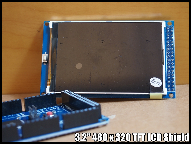
3.2" 480 x 320 TFT LCD Shield, install UTFT library and test with Arduino Mega 2560
It's 3.2" 480 x 320 TFT color screen support Arduino Mega 2560, named QDM320B.


According to the seller:
Overview
QD320DB16NT8357RA module is 3.2" TFT LCD with 262K color 480x320 resolutions.
The controller of this LCD module is HX8357B, it supports 16-wires DataBus interface. Moreover, this module includes the 5V -3.3V power conversion circuit and Level Level conversion circuit, This Module can Directly inserted into the Arduino Mega2560 Board, it also includes the SD card socket and SPI FLASH circuit.
Features
This video show how to install UTFT library (from http://www.rinkydinkelectronics.com/) and test example on Arduino Mega 2560.
More examples:
- Draw bitmap on 3.2" 480 x 320 TFT LCD Shield using UTFT
- Arduino Mega read string from Serial, display on 3.2" 480 x 320 TFT LCD Shield


According to the seller:
Overview
QD320DB16NT8357RA module is 3.2" TFT LCD with 262K color 480x320 resolutions.
The controller of this LCD module is HX8357B, it supports 16-wires DataBus interface. Moreover, this module includes the 5V -3.3V power conversion circuit and Level Level conversion circuit, This Module can Directly inserted into the Arduino Mega2560 Board, it also includes the SD card socket and SPI FLASH circuit.
Features
- Support Arduino Mega2560 Directly inserted
- With Full-angle IPS TFT panel
- OnBorad level conversion chip for 5V/3.3V MCU
- Compatible with 3.3/5V operation voltage level
- Compatible with Arduino-Series development Board.
- Compatible with UTFT / UTFT_Buttons /Utouch Library for arduino.
- provided 12-examples with Arduino ,3-examples with STM32
- With SD Card Socket
- With SPI FLASH circuit
This video show how to install UTFT library (from http://www.rinkydinkelectronics.com/) and test example on Arduino Mega 2560.
More examples:
- Draw bitmap on 3.2" 480 x 320 TFT LCD Shield using UTFT
- Arduino Mega read string from Serial, display on 3.2" 480 x 320 TFT LCD Shield
Monday, June 13, 2016
Setup Eclipse with GCC ARM Embedded on 32 bit Ubuntu 16.04 i386
As I have a NUCLEO F401RE Development Board on the way, I try to setup Eclipse with GCC ARM Embedded on Ubuntu 16.04/VirtualBox. It's not my target development platform, just to evaluate Eclipse + GCC ARM Embedded, so I setup on VirtualBox. No flash program will be included.

- Install Eclipse IDE for C/C++ Developers:
Visit http://www.eclipse.org/ to download the 32 bit Eclipse Installer
- Download GCC ARM Embedded
https://launchpad.net/gcc-arm-embedded/+download
- Add GNU ARM Plug-ins to Eclipse IDE
http://gnuarmeclipse.sourceforge.net/updates
- Finally, you can try to new a ARM project in Eclipse
You have to enter the path to the "Cross GNU ARM Toolchain", it's the bin folder of the GCC ARM Embedded downloaded before.
Cross-post in my another blogspot Embedded things.

In the beginning, I tried to do it on 64 bit Ubuntu, but found something wrong in the compiler, such as "Type 'uint32_t' could not be resolved"! I found many suggestion on Internet, but no perfect solution. Then I tried on 32 bit Ubuntu 16.04 i386. It can compile the example code without any problem.
- Ubuntu 16.04 come with gcc, g++ and make installed by default.
- To install Eclipse, jdk is required. To install Oracle Java 8 on Ubuntu, enter the commands:
$ sudo add-apt-repository ppa:webupd8team/java
$ sudo apt-get update
$ sudo apt-get install oracle-java8-installer
This video show how to, but on 64 bit Ubuntu (same procedure):
- Install Eclipse IDE for C/C++ Developers:
Visit http://www.eclipse.org/ to download the 32 bit Eclipse Installer
- Download GCC ARM Embedded
https://launchpad.net/gcc-arm-embedded/+download
- Add GNU ARM Plug-ins to Eclipse IDE
http://gnuarmeclipse.sourceforge.net/updates
- Finally, you can try to new a ARM project in Eclipse
You have to enter the path to the "Cross GNU ARM Toolchain", it's the bin folder of the GCC ARM Embedded downloaded before.
Cross-post in my another blogspot Embedded things.
Friday, June 10, 2016
NUCLEO-F401RE Nucleo STM32 Development Board STM32F401RE Integrate ST-LINK/V2-1 Debugger/Programmer Support Arduino

Description
The STM32 Nucleo board provides an affordable and flexible way for users to try out new ideas and build prototypes with any STM32 microcontroller line, choosing from the various combinations of performance, power consumption and features. The Arduino? connectivity support and ST Morpho headers make it easy to expand the functionality of the STM32 Nucleo open development platform with a wide choice of specialized shields.
The STM32 Nucleo board does not require any separate probe as it integrates the ST-LINK/V2-1 debugger/programmer.?
The STM32 Nucleo board comes with the STM32 comprehensive software HAL library together with various packaged software examples, as well as direct access to mbed online resources.
Key Features
- STM32 microcontroller with LQFP64 package
- STM32F401RE
- Arduino Uno Revision 3 connectivity
- STMicroelectronics Morpho extension pin headers for full access to all STM32 I/Os
- On-board ST-LINK/V2-1 debugger/programmer with SWD connector
- selection-mode switch to use the kit as a standalone ST-LINK/V2-1
- USB VBUS or external source(3.3 V, 5 V, 7 - 12 V)
- Power management access point
Monday, June 6, 2016
Getting started with ARM mbed IDE using STM32 Nucleo platform
This video shows how to get started with ARM mbed Integrated Development Environment using STM32 Nucleo platform. It explains the steps to perform to get your nucleo platform ready to use on mbed. Then it is described through an example how used the IDE to develop an application based on the numerous projects availables form mbed community.
Find out more information: http://www.st.com/stm32nucleo
Find out more information: http://www.st.com/stm32nucleo
Saturday, June 4, 2016
Arduin Uno as ISP to burn Bootloader to Mega 2560

To burn bootloader to Arduino MEGA 2560 using Arduino Uno as ISP, connect Uno & MEGA as shown:

PC is connected to Uno.
- Program Uno as ArduinoISP
> Select board of Uno
> Select programmer of AVRISP mkII
> File > Examples > ArduinoISP > ArduinoISP
> Upload
- Now we are going to program MEGA, the Uno act as Arduino as ISP.
> Select board of MEGA
> Select programmer of Arduino as ISP
> Tools > Burn Bootloader
As shown in this video:
Thursday, June 2, 2016
AnyPixel.js, an open-source software and hardware library to create big, unusual, interactive displays
AnyPixel.js is an open source software and hardware library created here at Google, making it possible to use the web to create big, unusual, interactive displays out of all kinds of things. Anyone can take the code and the schematics to create their own display at any scale or level of expertise.
The first display using this platform is in the 8th Avenue lobby at the Google NYC office. To create this installation, we used 5880 off-the-shelf arcade buttons as our pixels.
Learn more about the project and how to create your own AnyPixel.js display at https://goo.gl/anypixel
Sunday, May 22, 2016
“IoT: The Struggle for Meaning” by Massimo Banzi
Massimo Banzi explores the Internet of Things during an Arduino Day 2016 talk in Berkeley, CA.
Wednesday, May 11, 2016
I2C 4x20 LCD, test on Arduino Uno using LiquidCrystal_I2C library


Test I2C 4x20 LCD on Arduino Uno using LiquidCrystal_I2C library. marcoschwartz/LiquidCrystal_I2C is a LiquidCrystal Arduino library for the DFRobot I2C LCD displays.
- Install LiquidCrystal_I2C library in Arduino Software:

- Open the example of LiquidCrystal_I2C > HelloWorld

//YWROBOT
//Compatible with the Arduino IDE 1.0
//Library version:1.1
#include <Wire.h>
#include <LiquidCrystal_I2C.h>

LiquidCrystal_I2C lcd(0x27,20,4);  // set the LCD address to 0x27 for a 16 chars and 2 line display

void setup()
{
  lcd.init();                      // initialize the lcd
  lcd.init();
  // Print a message to the LCD.
  lcd.backlight();
  lcd.setCursor(3,0);
  lcd.print("Hello, world!");
  lcd.setCursor(2,1);
  lcd.print("Ywrobot Arduino!");
   lcd.setCursor(0,2);
  lcd.print("Arduino LCM IIC 2004");
   lcd.setCursor(2,3);
  lcd.print("Power By Ec-yuan!");
}


void loop()
{
}
Test with Arduino Uno:
Uno A4 (SDA) - SDA
Uno A5 (SCL) - SCL
Uno +5V - VCC
Uno GND - GND
Remark:
- It's a jumper on the daughter board on the back side, it have to be insert (short) to turn on the back light.
- Most probably you have to adjust the potentiometer on the daughter board to make the LCD characters clear.
- The I2C address of the board is 0x27, you can check it with i2cdetect library.
i2cdetect library - Arduino library to I2C bus for devices.
mcauser/i2cdetect is a Arduino library for scanning I2C bus for devices. Outputs a table similar to the linux program (i2cdetect - detect I2C chips) of the same name.
- Add i2cdetect library:
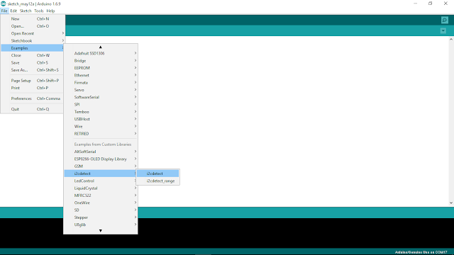
Open Library Manager (Sketch > Include Library > Manager Libraries...) to install i2cdetect library

- Open i2cdetect example (File > Examples > i2cdetect > i2cdetect)
i2cdetect.ino
Output example to shown a I2C device with address 0x27 is connected.
- Run on Arduino Uno
- A4 (SDA), A5 (SCL)

- Add i2cdetect library:
Open Library Manager (Sketch > Include Library > Manager Libraries...) to install i2cdetect library

- Open i2cdetect example (File > Examples > i2cdetect > i2cdetect)

i2cdetect.ino
#include <Wire.h>
#include <i2cdetect.h>

void setup() {
  Wire.begin();
  Serial.begin(9600);
  Serial.println("i2cdetect example\n");
  Serial.print("Scanning address range 0x03-0x77\n\n");
}

void loop() {
  i2cdetect();  // default range from 0x03 to 0x77
  delay(2000);
}
Output example to shown a I2C device with address 0x27 is connected.
- Run on Arduino Uno
- A4 (SDA), A5 (SCL)

Tuesday, May 10, 2016
NodeMCU/ESP8266 WebSocketsServer, load html from separate file in flash file system
This example have the same function of "NodeMCU/ESP8266 implement WebSocketsServer to control RGB LED", but the html is saved in separate file in flash file system instead of hard code in ino.

Prepare the html in data directory under sketch directory:
data/home.html
<html>
<head>
<script>
var connection = new WebSocket('ws://'+location.hostname+':81/', ['arduino']);
connection.onopen = function(){
    connection.send('Connect ' + new Date());
};

connection.onerror = function(error){
    console.log('WebSocket Error ', error);
};

connection.onmessage = function(e){
    console.log('Server: ', e.data);
};

function sendRGB(){
    var r = parseInt(document.getElementById('r').value).toString(16);
    var g = parseInt(document.getElementById('g').value).toString(16);
    var b = parseInt(document.getElementById('b').value).toString(16);

    if(r.length < 2){
        r = '0' + r;
    }

    if(g.length < 2){
        g = '0' + g;
    }

    if(b.length < 2){
        b = '0' + b;
    }

    var rgb = '#'+r+g+b;
    console.log('RGB: ' + rgb);
    connection.send(rgb);
}
</script>
</head>
<body>
<b>LED Control 2:</b><br/>
<i>Load html from separate file</i><br/>
<br/>
R: <input id="r" type="range" min="0" max="255" step="1" onchange="sendRGB();" /><br/>
G: <input id="g" type="range" min="0" max="255" step="1" onchange="sendRGB();" /><br/>
B: <input id="b" type="range" min="0" max="255" step="1" onchange="sendRGB();" /><br/>
<br/>
http://arduino-er.blogspot.com/
</body>
</html>
To upload this sketch data of html, refer last post "NodeMCU/ESP8266 read from separate file in Flash File System".
Modify the ino to load String of html from external file.
WebSocketServer_LEDcontrol.ino
//NodeMCU/ESP8266 implement WebSocketsServer to control RGB LED
//arduino-er.blogspot.com

#include <Arduino.h>

#include <ESP8266WiFi.h>
#include <ESP8266WiFiMulti.h>
#include <WebSocketsServer.h>
#include <ESP8266WebServer.h>
#include <ESP8266mDNS.h>
#include <Hash.h>

#include "FS.h"

#define LED_RED     15
#define LED_GREEN   12
#define LED_BLUE    13

ESP8266WiFiMulti WiFiMulti;

ESP8266WebServer server = ESP8266WebServer(80);
WebSocketsServer webSocket = WebSocketsServer(81);

String html_home;

void webSocketEvent(uint8_t num, WStype_t type, uint8_t * payload, size_t lenght) {

    switch(type) {
        case WStype_DISCONNECTED:
            Serial.printf("[%u] Disconnected!\n", num);
            break;
        case WStype_CONNECTED: {
            IPAddress ip = webSocket.remoteIP(num);
            Serial.printf("[%u] Connected from %d.%d.%d.%d url: %s\n", num, ip[0], ip[1], ip[2], ip[3], payload);

            // send message to client
            webSocket.sendTXT(num, "Connected");
        }
            break;
        case WStype_TEXT:
            Serial.printf("[%u] get Text: %s\n", num, payload);

            if(payload[0] == '#') {
                // we get RGB data

                // decode rgb data
                uint32_t rgb = (uint32_t) strtol((const char *) &payload[1], NULL, 16);

                analogWrite(LED_RED,    ((rgb >> 16) & 0xFF));
                analogWrite(LED_GREEN,  ((rgb >> 8) & 0xFF));
                analogWrite(LED_BLUE,   ((rgb >> 0) & 0xFF));
            }

            break;
    }

}

void prepareFile(){

  Serial.println("Prepare file system");
  SPIFFS.begin();

  File file = SPIFFS.open("/home.html", "r");
  if (!file) {
    Serial.println("file open failed");
  } else{
    Serial.println("file open success");

    html_home = "";
    while (file.available()) {
      //Serial.write(file.read());
      String line = file.readStringUntil('\n');
      html_home += line + "\n";
    }
    file.close();

    Serial.print(html_home);
  }
}

void setup() {
    //Serial.begin(921600);
    Serial.begin(115200);

    //Serial.setDebugOutput(true);

    Serial.println();
    Serial.println();
    Serial.println();

    for(uint8_t t = 4; t > 0; t--) {
        Serial.printf("[SETUP] BOOT WAIT %d...\n", t);
        Serial.flush();
        delay(1000);
    }

    pinMode(LED_RED, OUTPUT);
    pinMode(LED_GREEN, OUTPUT);
    pinMode(LED_BLUE, OUTPUT);

    digitalWrite(LED_RED, 1);
    digitalWrite(LED_GREEN, 1);
    digitalWrite(LED_BLUE, 1);


    prepareFile();

    WiFi.softAP("arduino-er", "12345678");
    IPAddress myIP = WiFi.softAPIP();
    Serial.print("AP IP address: ");
    Serial.println(myIP);

    // start webSocket server
    webSocket.begin();
    webSocket.onEvent(webSocketEvent);

    if(MDNS.begin("esp8266")) {
        Serial.println("MDNS responder started");
    }

    // handle index
    server.on("/", []() {
        // send home.html
        server.send(200, "text/html", html_home);
    });

    server.begin();

    // Add service to MDNS
    MDNS.addService("http", "tcp", 80);
    MDNS.addService("ws", "tcp", 81);

    digitalWrite(LED_RED, 0);
    digitalWrite(LED_GREEN, 0);
    digitalWrite(LED_BLUE, 0);

    Serial.printf("Server Start\n");

}

void loop() {
    webSocket.loop();
    server.handleClient();
}
- more example of "ESP8266 core for Arduino".
NodeMCU/ESP8266 read from separate file in Flash File System

This example show how NodeMCU/ESP8266 read separate file in Flash File System.
In order to upload extra files to NodeMCU/ESP8266, a tool "ESP8266FS" is needed:
ESP8266FS is a tool which integrates into the Arduino IDE. It adds a menu item to Tools menu for uploading the contents of sketch data directory into ESP8266 flash file system.
- Download the tool: https://github.com/esp8266/arduino-esp8266fs-plugin/releases/download/0.2.0/ESP8266FS-0.2.0.zip.
- In your Arduino sketchbook directory, create tools directory if it doesn't exist yet
- Unpack the tool into tools directory (the path will look like <home_dir>/Arduino/tools/ESP8266FS/tool/esp8266fs.jar)
- Restart Arduino IDE
- Open a sketch (or create a new one and save it)
- Go to sketch directory (choose Sketch > Show Sketch Folder)
- Create a directory named data and any files you want in the file system there
- Make sure you have selected a board, port, and closed Serial Monitor
- Select Tools > ESP8266 Sketch Data Upload. This should start uploading the files into ESP8266 flash file system. When done, IDE status bar will display SPIFFS Image Uploaded message.
This video show how to:
Example to read text file, test.txt, from Flash File System:
ESP_ext_file.ino
//arduino-er.blogspot.com
//To read separate file in file system
#include "FS.h"

void prepareFile(){

  Serial.println("Prepare file system");
  SPIFFS.begin();

  File file = SPIFFS.open("/test.txt", "r");
  if (!file) {
    Serial.println("file open failed!");
  } else{
    Serial.println("file open success:)");

    while (file.available()) {
      Serial.write(file.read());
    }
    file.close();
  }
}

void setup() {
  Serial.begin(115200);
  Serial.println("To read separate file in file system");
  prepareFile();
}

void loop() {
  // put your main code here, to run repeatedly:

}
ARDUINO 1.6.9 is available now

ARDUINO 1.6.9 is available, download the Arduino Software now.

Release Notes:
https://www.arduino.cc/en/Main/ReleaseNotes
ARDUINO 1.6.9 2016.05.10
[ide]
* Catch and report errors during parsing contributed index files
* Fixed IDE version color on about dialog box. Thanks @ivanebernal
* The "always-on-top update notification" popup is now less intrusive.
* Fixed untraslated string during IDE startup splash window. Thanks @ivanebernal
* New arduino-builder: better core library detection, faster operations when recompiling and more.
See https://github.com/arduino/arduino-builder/compare/1.3.9...1.3.15
* Fixed multitab error reporting
* Rework serial port discovery to be faster, less cpu intensive and FTDI friendly
* Avoid launching multiple concurrent compile and upload operation
* Use hi-res icons for Serial monitor and plotter
* Make http://librarymanager and http://boardmanager links clickable from the editor window
* Cut/Copy actions are disable when there is no text selected. Thanks @avargas-nearsoft
* Added more OSX native (emacs-like) keybindings. Thanks @nopdotcom
* Fixed Ctrl+Del: now deletes the word behind the cursor instead of the entire line. Thanks @avargas-nearsoft
* Fixed "Verify code after upload" option in preferences. Thanks @gh-megabit
[core]
* String class now supports iterators. Thanks @Chris--A
* sam: Allow 3rd party boards that depend on SAM core to use their own
USB vid/pid and manufacturer/product strings. Thanks @philmanofsky.
* avr: Check at runtime if 32u4 boards are shipped with new bootloader; if so
write bootloader magic value in an unproblematic RAM location
* avr, sam: Added "reciper.ar.pattern" to plaform.txt to allow compatibility
with older version of Arduino IDE. Thanks @per1234
[libraries]
* Bridge / bridge.py: added support for SSL sockets (Yun firmware >=1.6.2 is
needed).
Saturday, May 7, 2016
NodeMCU/ESP8266 implement WebSocketsServer to control RGB LED

In the previous example "NodeMCU/ESP8266 act as AP (Access Point) and web server to control GPIO", every time user click to change GPIO the page will be reloaded. This example use WebSocket, such that no need reload page.
Add WebSockets library to Arduino Software. To run on ESP devices, add version 2.x.x.
reference: https://github.com/Links2004/arduinoWebSockets

Open WebSockets example WebSocketServer_LEDcontrol. It's a WebSocketServer example to control RGB LED.

In my case, it cannot connect to my HotSpot shared by ASUS Zenfone 2 running Android 5.0! So I modify it to act as Access Point (AP).
WebSocketServer_LEDcontrol.ino
/*
 * WebSocketServer_LEDcontrol.ino
 *
 *  Created on: 26.11.2015
 *
 */
//Modified to act as AP
//arduino-er.blogspot.com

#include <Arduino.h>

#include <ESP8266WiFi.h>
#include <ESP8266WiFiMulti.h>
#include <WebSocketsServer.h>
#include <ESP8266WebServer.h>
#include <ESP8266mDNS.h>
#include <Hash.h>

#define LED_RED     15
#define LED_GREEN   12
#define LED_BLUE    13

#define USE_SERIAL Serial


ESP8266WiFiMulti WiFiMulti;

ESP8266WebServer server = ESP8266WebServer(80);
WebSocketsServer webSocket = WebSocketsServer(81);

void webSocketEvent(uint8_t num, WStype_t type, uint8_t * payload, size_t lenght) {

    switch(type) {
        case WStype_DISCONNECTED:
            USE_SERIAL.printf("[%u] Disconnected!\n", num);
            break;
        case WStype_CONNECTED: {
            IPAddress ip = webSocket.remoteIP(num);
            USE_SERIAL.printf("[%u] Connected from %d.%d.%d.%d url: %s\n", num, ip[0], ip[1], ip[2], ip[3], payload);

            // send message to client
            webSocket.sendTXT(num, "Connected");
        }
            break;
        case WStype_TEXT:
            USE_SERIAL.printf("[%u] get Text: %s\n", num, payload);

            if(payload[0] == '#') {
                // we get RGB data

                // decode rgb data
                uint32_t rgb = (uint32_t) strtol((const char *) &payload[1], NULL, 16);

                analogWrite(LED_RED,    ((rgb >> 16) & 0xFF));
                analogWrite(LED_GREEN,  ((rgb >> 8) & 0xFF));
                analogWrite(LED_BLUE,   ((rgb >> 0) & 0xFF));
            }

            break;
    }

}

void setup() {
    //USE_SERIAL.begin(921600);
    USE_SERIAL.begin(115200);

    //USE_SERIAL.setDebugOutput(true);

    USE_SERIAL.println();
    USE_SERIAL.println();
    USE_SERIAL.println();

    for(uint8_t t = 4; t > 0; t--) {
        USE_SERIAL.printf("[SETUP] BOOT WAIT %d...\n", t);
        USE_SERIAL.flush();
        delay(1000);
    }

    pinMode(LED_RED, OUTPUT);
    pinMode(LED_GREEN, OUTPUT);
    pinMode(LED_BLUE, OUTPUT);

    digitalWrite(LED_RED, 1);
    digitalWrite(LED_GREEN, 1);
    digitalWrite(LED_BLUE, 1);

    /*
    WiFiMulti.addAP("SSID", "passpasspass");

    while(WiFiMulti.run() != WL_CONNECTED) {
        delay(100);
    }
    */

    WiFi.softAP("arduino-er", "12345678");
    IPAddress myIP = WiFi.softAPIP();
    USE_SERIAL.print("AP IP address: ");
    USE_SERIAL.println(myIP);

    // start webSocket server
    webSocket.begin();
    webSocket.onEvent(webSocketEvent);

    if(MDNS.begin("esp8266")) {
        USE_SERIAL.println("MDNS responder started");
    }

    // handle index
    server.on("/", []() {
        // send index.html
        // replace for better looking
        server.send(200, "text/html",
        "<html><head><script>"
        "var connection = new WebSocket('ws://'+location.hostname+':81/', ['arduino']);"
        "connection.onopen = function () {  connection.send('Connect ' + new Date()); };"
        "connection.onerror = function (error) {    console.log('WebSocket Error ', error);};"
        "connection.onmessage = function (e) {  console.log('Server: ', e.data);};"
        "function sendRGB() {  "
        "var r = parseInt(document.getElementById('r').value).toString(16);  "
        "var g = parseInt(document.getElementById('g').value).toString(16);  "
        "var b = parseInt(document.getElementById('b').value).toString(16);  "
        "if(r.length < 2) { r = '0' + r; }   "
        "if(g.length < 2) { g = '0' + g; }   "
        "if(b.length < 2) { b = '0' + b; }   "
        "var rgb = '#'+r+g+b;    "
        "console.log('RGB: ' + rgb); "
        "connection.send(rgb); }"
        "</script></head><body>"
        "LED Control:<br/><br/>"
        "R: ""<input id=\"r\" type=\"range\" min=\"0\" max=\"255\" step=\"1\" onchange=\"sendRGB();\" /><br/>"
        "G: <input id=\"g\" type=\"range\" min=\"0\" max=\"255\" step=\"1\" onchange=\"sendRGB();\" /><br/>"
        "B: <input id=\"b\" type=\"range\" min=\"0\" max=\"255\" step=\"1\" onchange=\"sendRGB();\" /><br/>"
        "</body></html>");
    });

    server.begin();

    // Add service to MDNS
    MDNS.addService("http", "tcp", 80);
    MDNS.addService("ws", "tcp", 81);

    digitalWrite(LED_RED, 0);
    digitalWrite(LED_GREEN, 0);
    digitalWrite(LED_BLUE, 0);

}

void loop() {
    webSocket.loop();
    server.handleClient();
}
Connection:


Connect your mobile to the AP "arduino-er" with password "12345678", open browser and visit IP 192.168.4.1. Then you can control the RGB LED in web page. As shown in the video, more than one device can connect to and control the RGB LED at the same time.
This example hard-code the html inside ino. The next example show how to "load html from separate file in flash file system".
- more example of "ESP8266 core for Arduino".
Updated@2017-06-18:
What is WStype_t (WStype_DISCONNECTED, WStype_CONNECTED...)?
WStype_t is:
typedef enum {
    WStype_ERROR,
    WStype_DISCONNECTED,
    WStype_CONNECTED,
    WStype_TEXT,
    WStype_BIN
} WStype_t;
Should be defined at your Documents\Arduino\libraries\WebSockets\src\WebSockets.h

You should have a example at File > Examples > WebSockets > WebSocketClient to show how to use it.


Subscribe to:
Posts (Atom)