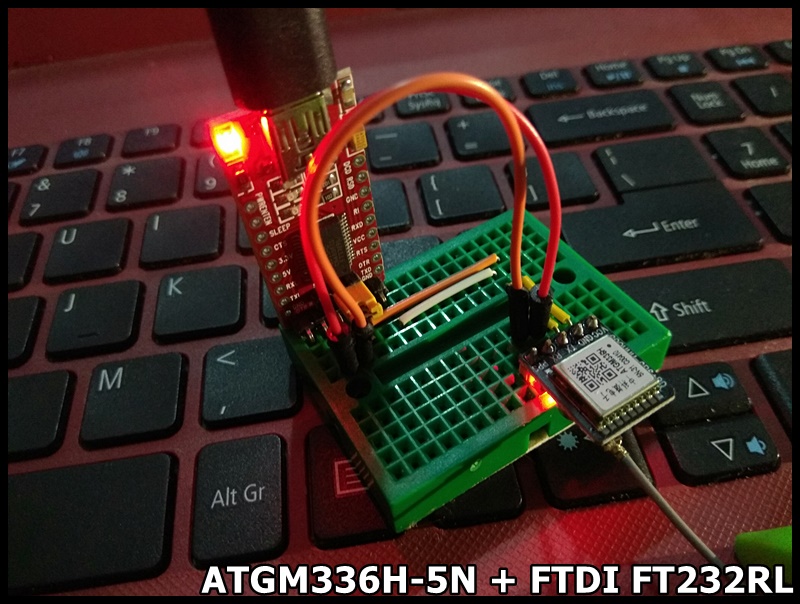
To read ATGM336H-5N GNSS Module from ESP32/ESP8266, or Arduino, the TinyGPS++ library can be use.
TinyGPS++ is a new Arduino library for parsing NMEA data streams provided by GPS modules. To install this library, download here, unzip the archive into the Arduino “libraries” folder, and restart Arduino. You should rename the folder “TinyGPSPlus”.
The TinyGPS++ connect GPS module using SoftwareSerial. To make it work on ESP32, install EspSoftwareSerial in Arduino IDE Library Manager.
Now you can open TinyGps++ DeviceExample.
Modify the RXPin and TXPin to match with you connection. It's 16 and 17 in my case. And change GPSBaud to 9600.
It's a 1.3 inch 240x240 IPS LCD, with driver ST7789 using SPI interface.
7 pins are used to connect to MCU:
#Pin LabelDescription
1GNDLCD Power ground
2VCCLCD power supply is positive (3.3V)
3SCLLCD SPI bus clock signal - connect to ESP32 18 TFT_SCLK
4SDALCD SPI bus write data signal - connect to ESP32 23 TFT_MOSI
5RES LCD reset control signal(Low level reset) - connect to ESP32 4 TFT_RST
6DC LCD register/data - connect to EST32 2 TFT_DC
7BLKLCD backlight control signal - Connect to 3.3V
This video show how to setup on Arduino IDE, using TFT_eSPI library on ESP32 (ESP32-DevKitC), to drive the 1.3 inch 240x240 IPS LCD.
Using TFT_eSPI, if you load a new copy of TFT_eSPI then it will over-write your setups if they are kept within the TFT_eSPI folder. It's suggested to create a new folder in your Arduino library folder called "TFT_eSPI_Setups". You then place your custom setup.h (Setup24_ST7789_ESP32.h in my exercise) files in there. After an upgrade simply edit the User_Setup_Select.h file to point to your custom setup file. (ref: https://github.com/Bodmer/TFT_eSPI)
- Makesure TFT_eSPI library is installed in Arduino IDE.
- Create "TFT_eSPI_Setups" folder under your Arduino library folder.
- Copy the file TFT_eSPI/User_Setups/Setup24_ST7789.h to TFT_eSPI_Setups folder, re-name it Setup24_ST7789_ESP32.h.
- Edit Setup24_ST7789_ESP32.h to match our connection:
- Edit User_Setup_Select.h file to point to the custom setup file, Setup24_ST7789_ESP32.h.
One of the very useful feature of ESP32/ESP8266 is OTA (Over-The-Air) programming; such that you can update the firmware without physically connect to the device.
With ESP32/ESP8266 core for Arduino installed to your Arduino IDE, you can find ArduinoOTA examples of BasicaOTA and OTAWebUpdater under Examples for ESP32 Dev Module.
This post show trying BasicOTA examples on ESP32-DevKitC using Arduino IDE running on Windows 10, and fix the problem I faced: Network Ports no shown and No response from device.
Basically, the default DevKitC firmware have no OTA function. So you have to flash the first firmware with OTA function using serial port (USB). After then, you can update your firmware via OTA without physical connected serial port. Both the computer used to update the firmware and the ESP devices to be updated have to be in the same network.
The ESP device I used in this example is ESP32-DevKitC with ESP32-WROOM-32 module. It should be a relatively old and original version.
Somebody (include me) reported there are no Network Ports shown up.
Somebody suggested to install Python, somebody suggested to reboot router, or install Bonjour... All of them not work for me. In order to eliminate the problem outside my computer, I decide to use Windows 10's Mobile hotspot.
Open BasicOTA example and change ssid and password according to my network setting. Upload the ESP32 device via serial port (USB, or COM5 in this example).
Turn on Windows 10's Mobile hotspot with matched ssid/password.
Now the Network ports shown, with attached device (the programmed ESP32 with OTA function) and its assigned ip.
Once Network port selected, the Arduino IDE's Serial Monitor not work on network. So I run Putty to monitor the output from ESP device via serial port.
Now, upload your second program via OTA. But still fail due to No response from device.
Now, open Windows Security and Allow espota.exe to communicate through Windows Defender Firewall.
Upload again, and Done uploading.
(In the various steps, the assigned ip of the ESP device may be changed. Double check the ip in Putty and select the Network port accordingly.)