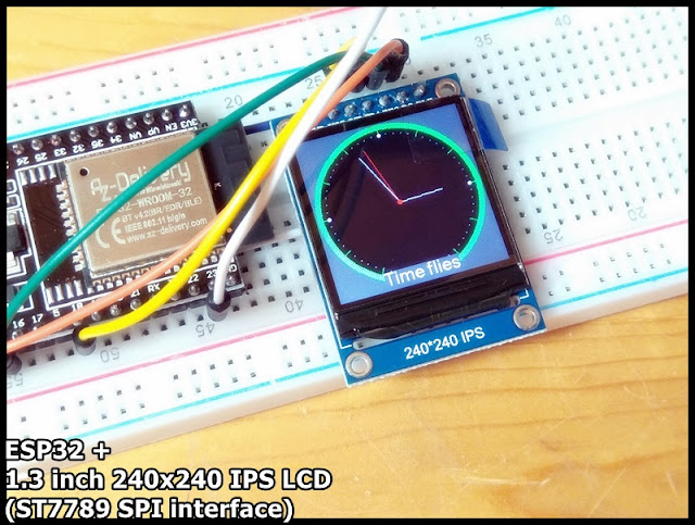
It's a 1.3 inch 240x240 IPS LCD, with driver ST7789 using SPI interface.
7 pins are used to connect to MCU:
# Pin Label Description
1 GND LCD Power ground
2 VCC LCD power supply is positive (3.3V)
3 SCL LCD SPI bus clock signal - connect to ESP32 18 TFT_SCLK
4 SDA LCD SPI bus write data signal - connect to ESP32 23 TFT_MOSI
5 RES LCD reset control signal(Low level reset) - connect to ESP32 4 TFT_RST
6 DC LCD register/data - connect to EST32 2 TFT_DC
7 BLK LCD backlight control signal - Connect to 3.3V
Product page: lcdwiki : 1.3inch IPS Module
This video show how to setup on Arduino IDE, using TFT_eSPI library on ESP32 (ESP32-DevKitC), to drive the 1.3 inch 240x240 IPS LCD.
Using TFT_eSPI, if you load a new copy of TFT_eSPI then it will over-write your setups if they are kept within the TFT_eSPI folder. It's suggested to create a new folder in your Arduino library folder called "TFT_eSPI_Setups". You then place your custom setup.h (Setup24_ST7789_ESP32.h in my exercise) files in there. After an upgrade simply edit the User_Setup_Select.h file to point to your custom setup file. (ref: https://github.com/Bodmer/TFT_eSPI)
- Makesure TFT_eSPI library is installed in Arduino IDE.
- Create "TFT_eSPI_Setups" folder under your Arduino library folder.
- Copy the file TFT_eSPI/User_Setups/Setup24_ST7789.h to TFT_eSPI_Setups folder, re-name it Setup24_ST7789_ESP32.h.
- Edit Setup24_ST7789_ESP32.h to match our connection:
- Edit User_Setup_Select.h file to point to the custom setup file, Setup24_ST7789_ESP32.h.
- Then you can try examples of TFT_eSPI.


Thank you, it`s work!
ReplyDeleteHello.. Thnx for the help u provide here. I have a question plz. After all steps I had a fatal error saying that
ReplyDeletefatal error: SPIFFS.h: No such file or directory
#include "SPIFFS.h"
what shall I do at this point? ur help is highly appreciated..