Sunday, May 22, 2016
“IoT: The Struggle for Meaning” by Massimo Banzi
Massimo Banzi explores the Internet of Things during an Arduino Day 2016 talk in Berkeley, CA.
Wednesday, May 11, 2016
I2C 4x20 LCD, test on Arduino Uno using LiquidCrystal_I2C library


Test I2C 4x20 LCD on Arduino Uno using LiquidCrystal_I2C library. marcoschwartz/LiquidCrystal_I2C is a LiquidCrystal Arduino library for the DFRobot I2C LCD displays.
- Install LiquidCrystal_I2C library in Arduino Software:

- Open the example of LiquidCrystal_I2C > HelloWorld

//YWROBOT
//Compatible with the Arduino IDE 1.0
//Library version:1.1
#include <Wire.h>
#include <LiquidCrystal_I2C.h>

LiquidCrystal_I2C lcd(0x27,20,4);  // set the LCD address to 0x27 for a 16 chars and 2 line display

void setup()
{
  lcd.init();                      // initialize the lcd
  lcd.init();
  // Print a message to the LCD.
  lcd.backlight();
  lcd.setCursor(3,0);
  lcd.print("Hello, world!");
  lcd.setCursor(2,1);
  lcd.print("Ywrobot Arduino!");
   lcd.setCursor(0,2);
  lcd.print("Arduino LCM IIC 2004");
   lcd.setCursor(2,3);
  lcd.print("Power By Ec-yuan!");
}


void loop()
{
}
Test with Arduino Uno:
Uno A4 (SDA) - SDA
Uno A5 (SCL) - SCL
Uno +5V - VCC
Uno GND - GND
Remark:
- It's a jumper on the daughter board on the back side, it have to be insert (short) to turn on the back light.
- Most probably you have to adjust the potentiometer on the daughter board to make the LCD characters clear.
- The I2C address of the board is 0x27, you can check it with i2cdetect library.
i2cdetect library - Arduino library to I2C bus for devices.
mcauser/i2cdetect is a Arduino library for scanning I2C bus for devices. Outputs a table similar to the linux program (i2cdetect - detect I2C chips) of the same name.
- Add i2cdetect library:
Open Library Manager (Sketch > Include Library > Manager Libraries...) to install i2cdetect library

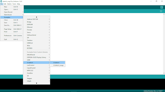
- Open i2cdetect example (File > Examples > i2cdetect > i2cdetect)
i2cdetect.ino
Output example to shown a I2C device with address 0x27 is connected.
- Run on Arduino Uno
- A4 (SDA), A5 (SCL)

- Add i2cdetect library:
Open Library Manager (Sketch > Include Library > Manager Libraries...) to install i2cdetect library

- Open i2cdetect example (File > Examples > i2cdetect > i2cdetect)

i2cdetect.ino
#include <Wire.h>
#include <i2cdetect.h>

void setup() {
  Wire.begin();
  Serial.begin(9600);
  Serial.println("i2cdetect example\n");
  Serial.print("Scanning address range 0x03-0x77\n\n");
}

void loop() {
  i2cdetect();  // default range from 0x03 to 0x77
  delay(2000);
}
Output example to shown a I2C device with address 0x27 is connected.
- Run on Arduino Uno
- A4 (SDA), A5 (SCL)

Tuesday, May 10, 2016
NodeMCU/ESP8266 WebSocketsServer, load html from separate file in flash file system
This example have the same function of "NodeMCU/ESP8266 implement WebSocketsServer to control RGB LED", but the html is saved in separate file in flash file system instead of hard code in ino.

Prepare the html in data directory under sketch directory:
data/home.html
<html>
<head>
<script>
var connection = new WebSocket('ws://'+location.hostname+':81/', ['arduino']);
connection.onopen = function(){
    connection.send('Connect ' + new Date());
};

connection.onerror = function(error){
    console.log('WebSocket Error ', error);
};

connection.onmessage = function(e){
    console.log('Server: ', e.data);
};

function sendRGB(){
    var r = parseInt(document.getElementById('r').value).toString(16);
    var g = parseInt(document.getElementById('g').value).toString(16);
    var b = parseInt(document.getElementById('b').value).toString(16);

    if(r.length < 2){
        r = '0' + r;
    }

    if(g.length < 2){
        g = '0' + g;
    }

    if(b.length < 2){
        b = '0' + b;
    }

    var rgb = '#'+r+g+b;
    console.log('RGB: ' + rgb);
    connection.send(rgb);
}
</script>
</head>
<body>
<b>LED Control 2:</b><br/>
<i>Load html from separate file</i><br/>
<br/>
R: <input id="r" type="range" min="0" max="255" step="1" onchange="sendRGB();" /><br/>
G: <input id="g" type="range" min="0" max="255" step="1" onchange="sendRGB();" /><br/>
B: <input id="b" type="range" min="0" max="255" step="1" onchange="sendRGB();" /><br/>
<br/>
http://arduino-er.blogspot.com/
</body>
</html>
To upload this sketch data of html, refer last post "NodeMCU/ESP8266 read from separate file in Flash File System".
Modify the ino to load String of html from external file.
WebSocketServer_LEDcontrol.ino
//NodeMCU/ESP8266 implement WebSocketsServer to control RGB LED
//arduino-er.blogspot.com

#include <Arduino.h>

#include <ESP8266WiFi.h>
#include <ESP8266WiFiMulti.h>
#include <WebSocketsServer.h>
#include <ESP8266WebServer.h>
#include <ESP8266mDNS.h>
#include <Hash.h>

#include "FS.h"

#define LED_RED     15
#define LED_GREEN   12
#define LED_BLUE    13

ESP8266WiFiMulti WiFiMulti;

ESP8266WebServer server = ESP8266WebServer(80);
WebSocketsServer webSocket = WebSocketsServer(81);

String html_home;

void webSocketEvent(uint8_t num, WStype_t type, uint8_t * payload, size_t lenght) {

    switch(type) {
        case WStype_DISCONNECTED:
            Serial.printf("[%u] Disconnected!\n", num);
            break;
        case WStype_CONNECTED: {
            IPAddress ip = webSocket.remoteIP(num);
            Serial.printf("[%u] Connected from %d.%d.%d.%d url: %s\n", num, ip[0], ip[1], ip[2], ip[3], payload);

            // send message to client
            webSocket.sendTXT(num, "Connected");
        }
            break;
        case WStype_TEXT:
            Serial.printf("[%u] get Text: %s\n", num, payload);

            if(payload[0] == '#') {
                // we get RGB data

                // decode rgb data
                uint32_t rgb = (uint32_t) strtol((const char *) &payload[1], NULL, 16);

                analogWrite(LED_RED,    ((rgb >> 16) & 0xFF));
                analogWrite(LED_GREEN,  ((rgb >> 8) & 0xFF));
                analogWrite(LED_BLUE,   ((rgb >> 0) & 0xFF));
            }

            break;
    }

}

void prepareFile(){

  Serial.println("Prepare file system");
  SPIFFS.begin();

  File file = SPIFFS.open("/home.html", "r");
  if (!file) {
    Serial.println("file open failed");
  } else{
    Serial.println("file open success");

    html_home = "";
    while (file.available()) {
      //Serial.write(file.read());
      String line = file.readStringUntil('\n');
      html_home += line + "\n";
    }
    file.close();

    Serial.print(html_home);
  }
}

void setup() {
    //Serial.begin(921600);
    Serial.begin(115200);

    //Serial.setDebugOutput(true);

    Serial.println();
    Serial.println();
    Serial.println();

    for(uint8_t t = 4; t > 0; t--) {
        Serial.printf("[SETUP] BOOT WAIT %d...\n", t);
        Serial.flush();
        delay(1000);
    }

    pinMode(LED_RED, OUTPUT);
    pinMode(LED_GREEN, OUTPUT);
    pinMode(LED_BLUE, OUTPUT);

    digitalWrite(LED_RED, 1);
    digitalWrite(LED_GREEN, 1);
    digitalWrite(LED_BLUE, 1);


    prepareFile();

    WiFi.softAP("arduino-er", "12345678");
    IPAddress myIP = WiFi.softAPIP();
    Serial.print("AP IP address: ");
    Serial.println(myIP);

    // start webSocket server
    webSocket.begin();
    webSocket.onEvent(webSocketEvent);

    if(MDNS.begin("esp8266")) {
        Serial.println("MDNS responder started");
    }

    // handle index
    server.on("/", []() {
        // send home.html
        server.send(200, "text/html", html_home);
    });

    server.begin();

    // Add service to MDNS
    MDNS.addService("http", "tcp", 80);
    MDNS.addService("ws", "tcp", 81);

    digitalWrite(LED_RED, 0);
    digitalWrite(LED_GREEN, 0);
    digitalWrite(LED_BLUE, 0);

    Serial.printf("Server Start\n");

}

void loop() {
    webSocket.loop();
    server.handleClient();
}
- more example of "ESP8266 core for Arduino".
NodeMCU/ESP8266 read from separate file in Flash File System

This example show how NodeMCU/ESP8266 read separate file in Flash File System.
In order to upload extra files to NodeMCU/ESP8266, a tool "ESP8266FS" is needed:
ESP8266FS is a tool which integrates into the Arduino IDE. It adds a menu item to Tools menu for uploading the contents of sketch data directory into ESP8266 flash file system.
- Download the tool: https://github.com/esp8266/arduino-esp8266fs-plugin/releases/download/0.2.0/ESP8266FS-0.2.0.zip.
- In your Arduino sketchbook directory, create tools directory if it doesn't exist yet
- Unpack the tool into tools directory (the path will look like <home_dir>/Arduino/tools/ESP8266FS/tool/esp8266fs.jar)
- Restart Arduino IDE
- Open a sketch (or create a new one and save it)
- Go to sketch directory (choose Sketch > Show Sketch Folder)
- Create a directory named data and any files you want in the file system there
- Make sure you have selected a board, port, and closed Serial Monitor
- Select Tools > ESP8266 Sketch Data Upload. This should start uploading the files into ESP8266 flash file system. When done, IDE status bar will display SPIFFS Image Uploaded message.
This video show how to:
Example to read text file, test.txt, from Flash File System:
ESP_ext_file.ino
//arduino-er.blogspot.com
//To read separate file in file system
#include "FS.h"

void prepareFile(){

  Serial.println("Prepare file system");
  SPIFFS.begin();

  File file = SPIFFS.open("/test.txt", "r");
  if (!file) {
    Serial.println("file open failed!");
  } else{
    Serial.println("file open success:)");

    while (file.available()) {
      Serial.write(file.read());
    }
    file.close();
  }
}

void setup() {
  Serial.begin(115200);
  Serial.println("To read separate file in file system");
  prepareFile();
}

void loop() {
  // put your main code here, to run repeatedly:

}
ARDUINO 1.6.9 is available now

ARDUINO 1.6.9 is available, download the Arduino Software now.

Release Notes:
https://www.arduino.cc/en/Main/ReleaseNotes
ARDUINO 1.6.9 2016.05.10
[ide]
* Catch and report errors during parsing contributed index files
* Fixed IDE version color on about dialog box. Thanks @ivanebernal
* The "always-on-top update notification" popup is now less intrusive.
* Fixed untraslated string during IDE startup splash window. Thanks @ivanebernal
* New arduino-builder: better core library detection, faster operations when recompiling and more.
See https://github.com/arduino/arduino-builder/compare/1.3.9...1.3.15
* Fixed multitab error reporting
* Rework serial port discovery to be faster, less cpu intensive and FTDI friendly
* Avoid launching multiple concurrent compile and upload operation
* Use hi-res icons for Serial monitor and plotter
* Make http://librarymanager and http://boardmanager links clickable from the editor window
* Cut/Copy actions are disable when there is no text selected. Thanks @avargas-nearsoft
* Added more OSX native (emacs-like) keybindings. Thanks @nopdotcom
* Fixed Ctrl+Del: now deletes the word behind the cursor instead of the entire line. Thanks @avargas-nearsoft
* Fixed "Verify code after upload" option in preferences. Thanks @gh-megabit
[core]
* String class now supports iterators. Thanks @Chris--A
* sam: Allow 3rd party boards that depend on SAM core to use their own
USB vid/pid and manufacturer/product strings. Thanks @philmanofsky.
* avr: Check at runtime if 32u4 boards are shipped with new bootloader; if so
write bootloader magic value in an unproblematic RAM location
* avr, sam: Added "reciper.ar.pattern" to plaform.txt to allow compatibility
with older version of Arduino IDE. Thanks @per1234
[libraries]
* Bridge / bridge.py: added support for SSL sockets (Yun firmware >=1.6.2 is
needed).
Saturday, May 7, 2016
NodeMCU/ESP8266 implement WebSocketsServer to control RGB LED

In the previous example "NodeMCU/ESP8266 act as AP (Access Point) and web server to control GPIO", every time user click to change GPIO the page will be reloaded. This example use WebSocket, such that no need reload page.
Add WebSockets library to Arduino Software. To run on ESP devices, add version 2.x.x.
reference: https://github.com/Links2004/arduinoWebSockets

Open WebSockets example WebSocketServer_LEDcontrol. It's a WebSocketServer example to control RGB LED.

In my case, it cannot connect to my HotSpot shared by ASUS Zenfone 2 running Android 5.0! So I modify it to act as Access Point (AP).
WebSocketServer_LEDcontrol.ino
/*
 * WebSocketServer_LEDcontrol.ino
 *
 *  Created on: 26.11.2015
 *
 */
//Modified to act as AP
//arduino-er.blogspot.com

#include <Arduino.h>

#include <ESP8266WiFi.h>
#include <ESP8266WiFiMulti.h>
#include <WebSocketsServer.h>
#include <ESP8266WebServer.h>
#include <ESP8266mDNS.h>
#include <Hash.h>

#define LED_RED     15
#define LED_GREEN   12
#define LED_BLUE    13

#define USE_SERIAL Serial


ESP8266WiFiMulti WiFiMulti;

ESP8266WebServer server = ESP8266WebServer(80);
WebSocketsServer webSocket = WebSocketsServer(81);

void webSocketEvent(uint8_t num, WStype_t type, uint8_t * payload, size_t lenght) {

    switch(type) {
        case WStype_DISCONNECTED:
            USE_SERIAL.printf("[%u] Disconnected!\n", num);
            break;
        case WStype_CONNECTED: {
            IPAddress ip = webSocket.remoteIP(num);
            USE_SERIAL.printf("[%u] Connected from %d.%d.%d.%d url: %s\n", num, ip[0], ip[1], ip[2], ip[3], payload);

            // send message to client
            webSocket.sendTXT(num, "Connected");
        }
            break;
        case WStype_TEXT:
            USE_SERIAL.printf("[%u] get Text: %s\n", num, payload);

            if(payload[0] == '#') {
                // we get RGB data

                // decode rgb data
                uint32_t rgb = (uint32_t) strtol((const char *) &payload[1], NULL, 16);

                analogWrite(LED_RED,    ((rgb >> 16) & 0xFF));
                analogWrite(LED_GREEN,  ((rgb >> 8) & 0xFF));
                analogWrite(LED_BLUE,   ((rgb >> 0) & 0xFF));
            }

            break;
    }

}

void setup() {
    //USE_SERIAL.begin(921600);
    USE_SERIAL.begin(115200);

    //USE_SERIAL.setDebugOutput(true);

    USE_SERIAL.println();
    USE_SERIAL.println();
    USE_SERIAL.println();

    for(uint8_t t = 4; t > 0; t--) {
        USE_SERIAL.printf("[SETUP] BOOT WAIT %d...\n", t);
        USE_SERIAL.flush();
        delay(1000);
    }

    pinMode(LED_RED, OUTPUT);
    pinMode(LED_GREEN, OUTPUT);
    pinMode(LED_BLUE, OUTPUT);

    digitalWrite(LED_RED, 1);
    digitalWrite(LED_GREEN, 1);
    digitalWrite(LED_BLUE, 1);

    /*
    WiFiMulti.addAP("SSID", "passpasspass");

    while(WiFiMulti.run() != WL_CONNECTED) {
        delay(100);
    }
    */

    WiFi.softAP("arduino-er", "12345678");
    IPAddress myIP = WiFi.softAPIP();
    USE_SERIAL.print("AP IP address: ");
    USE_SERIAL.println(myIP);

    // start webSocket server
    webSocket.begin();
    webSocket.onEvent(webSocketEvent);

    if(MDNS.begin("esp8266")) {
        USE_SERIAL.println("MDNS responder started");
    }

    // handle index
    server.on("/", []() {
        // send index.html
        // replace for better looking
        server.send(200, "text/html",
        "<html><head><script>"
        "var connection = new WebSocket('ws://'+location.hostname+':81/', ['arduino']);"
        "connection.onopen = function () {  connection.send('Connect ' + new Date()); };"
        "connection.onerror = function (error) {    console.log('WebSocket Error ', error);};"
        "connection.onmessage = function (e) {  console.log('Server: ', e.data);};"
        "function sendRGB() {  "
        "var r = parseInt(document.getElementById('r').value).toString(16);  "
        "var g = parseInt(document.getElementById('g').value).toString(16);  "
        "var b = parseInt(document.getElementById('b').value).toString(16);  "
        "if(r.length < 2) { r = '0' + r; }   "
        "if(g.length < 2) { g = '0' + g; }   "
        "if(b.length < 2) { b = '0' + b; }   "
        "var rgb = '#'+r+g+b;    "
        "console.log('RGB: ' + rgb); "
        "connection.send(rgb); }"
        "</script></head><body>"
        "LED Control:<br/><br/>"
        "R: ""<input id=\"r\" type=\"range\" min=\"0\" max=\"255\" step=\"1\" onchange=\"sendRGB();\" /><br/>"
        "G: <input id=\"g\" type=\"range\" min=\"0\" max=\"255\" step=\"1\" onchange=\"sendRGB();\" /><br/>"
        "B: <input id=\"b\" type=\"range\" min=\"0\" max=\"255\" step=\"1\" onchange=\"sendRGB();\" /><br/>"
        "</body></html>");
    });

    server.begin();

    // Add service to MDNS
    MDNS.addService("http", "tcp", 80);
    MDNS.addService("ws", "tcp", 81);

    digitalWrite(LED_RED, 0);
    digitalWrite(LED_GREEN, 0);
    digitalWrite(LED_BLUE, 0);

}

void loop() {
    webSocket.loop();
    server.handleClient();
}
Connection:


Connect your mobile to the AP "arduino-er" with password "12345678", open browser and visit IP 192.168.4.1. Then you can control the RGB LED in web page. As shown in the video, more than one device can connect to and control the RGB LED at the same time.
This example hard-code the html inside ino. The next example show how to "load html from separate file in flash file system".
- more example of "ESP8266 core for Arduino".
Updated@2017-06-18:
What is WStype_t (WStype_DISCONNECTED, WStype_CONNECTED...)?
WStype_t is:
typedef enum {
    WStype_ERROR,
    WStype_DISCONNECTED,
    WStype_CONNECTED,
    WStype_TEXT,
    WStype_BIN
} WStype_t;
Should be defined at your Documents\Arduino\libraries\WebSockets\src\WebSockets.h

You should have a example at File > Examples > WebSockets > WebSocketClient to show how to use it.


Friday, May 6, 2016
Arduino Uno + MAX7219 8x8 LED Matrix via SPI, using LedControl Library

We can add LedControl Library to Arduino IDE, to control 8*8 LED Matrix with MAX7219 via SPI. LedControl is a library for the MAX7219 and the MAX7221 Led display driver.
(ref: http://wayoda.github.io/LedControl/)

Open the File > Examples > LedControl > LCDemoMatrix
LCDemoMatrix.ino
//We always have to include the library
#include "LedControl.h"

/*
 Now we need a LedControl to work with.
 ***** These pin numbers will probably not work with your hardware *****
 pin 12 is connected to the DataIn
 pin 11 is connected to the CLK
 pin 10 is connected to LOAD
 We have only a single MAX72XX.
 */
LedControl lc=LedControl(12,11,10,1);

/* we always wait a bit between updates of the display */
unsigned long delaytime=100;

void setup() {
  /*
   The MAX72XX is in power-saving mode on startup,
   we have to do a wakeup call
   */
  lc.shutdown(0,false);
  /* Set the brightness to a medium values */
  lc.setIntensity(0,8);
  /* and clear the display */
  lc.clearDisplay(0);
}

/*
 This method will display the characters for the
 word "Arduino" one after the other on the matrix.
 (you need at least 5x7 leds to see the whole chars)
 */
void writeArduinoOnMatrix() {
  /* here is the data for the characters */
  byte a[5]={B01111110,B10001000,B10001000,B10001000,B01111110};
  byte r[5]={B00111110,B00010000,B00100000,B00100000,B00010000};
  byte d[5]={B00011100,B00100010,B00100010,B00010010,B11111110};
  byte u[5]={B00111100,B00000010,B00000010,B00000100,B00111110};
  byte i[5]={B00000000,B00100010,B10111110,B00000010,B00000000};
  byte n[5]={B00111110,B00010000,B00100000,B00100000,B00011110};
  byte o[5]={B00011100,B00100010,B00100010,B00100010,B00011100};

  /* now display them one by one with a small delay */
  lc.setRow(0,0,a[0]);
  lc.setRow(0,1,a[1]);
  lc.setRow(0,2,a[2]);
  lc.setRow(0,3,a[3]);
  lc.setRow(0,4,a[4]);
  delay(delaytime);
  lc.setRow(0,0,r[0]);
  lc.setRow(0,1,r[1]);
  lc.setRow(0,2,r[2]);
  lc.setRow(0,3,r[3]);
  lc.setRow(0,4,r[4]);
  delay(delaytime);
  lc.setRow(0,0,d[0]);
  lc.setRow(0,1,d[1]);
  lc.setRow(0,2,d[2]);
  lc.setRow(0,3,d[3]);
  lc.setRow(0,4,d[4]);
  delay(delaytime);
  lc.setRow(0,0,u[0]);
  lc.setRow(0,1,u[1]);
  lc.setRow(0,2,u[2]);
  lc.setRow(0,3,u[3]);
  lc.setRow(0,4,u[4]);
  delay(delaytime);
  lc.setRow(0,0,i[0]);
  lc.setRow(0,1,i[1]);
  lc.setRow(0,2,i[2]);
  lc.setRow(0,3,i[3]);
  lc.setRow(0,4,i[4]);
  delay(delaytime);
  lc.setRow(0,0,n[0]);
  lc.setRow(0,1,n[1]);
  lc.setRow(0,2,n[2]);
  lc.setRow(0,3,n[3]);
  lc.setRow(0,4,n[4]);
  delay(delaytime);
  lc.setRow(0,0,o[0]);
  lc.setRow(0,1,o[1]);
  lc.setRow(0,2,o[2]);
  lc.setRow(0,3,o[3]);
  lc.setRow(0,4,o[4]);
  delay(delaytime);
  lc.setRow(0,0,0);
  lc.setRow(0,1,0);
  lc.setRow(0,2,0);
  lc.setRow(0,3,0);
  lc.setRow(0,4,0);
  delay(delaytime);
}

/*
  This function lights up a some Leds in a row.
 The pattern will be repeated on every row.
 The pattern will blink along with the row-number.
 row number 4 (index==3) will blink 4 times etc.
 */
void rows() {
  for(int row=0;row<8;row++) {
    delay(delaytime);
    lc.setRow(0,row,B10100000);
    delay(delaytime);
    lc.setRow(0,row,(byte)0);
    for(int i=0;i<row;i++) {
      delay(delaytime);
      lc.setRow(0,row,B10100000);
      delay(delaytime);
      lc.setRow(0,row,(byte)0);
    }
  }
}

/*
  This function lights up a some Leds in a column.
 The pattern will be repeated on every column.
 The pattern will blink along with the column-number.
 column number 4 (index==3) will blink 4 times etc.
 */
void columns() {
  for(int col=0;col<8;col++) {
    delay(delaytime);
    lc.setColumn(0,col,B10100000);
    delay(delaytime);
    lc.setColumn(0,col,(byte)0);
    for(int i=0;i<col;i++) {
      delay(delaytime);
      lc.setColumn(0,col,B10100000);
      delay(delaytime);
      lc.setColumn(0,col,(byte)0);
    }
  }
}

/*
 This function will light up every Led on the matrix.
 The led will blink along with the row-number.
 row number 4 (index==3) will blink 4 times etc.
 */
void single() {
  for(int row=0;row<8;row++) {
    for(int col=0;col<8;col++) {
      delay(delaytime);
      lc.setLed(0,row,col,true);
      delay(delaytime);
      for(int i=0;i<col;i++) {
        lc.setLed(0,row,col,false);
        delay(delaytime);
        lc.setLed(0,row,col,true);
        delay(delaytime);
      }
    }
  }
}

void loop() {
  writeArduinoOnMatrix();
  rows();
  columns();
  single();
}
Connect MAX7219 8x8 LED Matrix to Arduino Uno as stated in the example:
- pin 12 is connected to the DataIn
- pin 11 is connected to the CLK
- pin 10 is connected to LOAD (it's cs marked on my sample)
- +5V to VCC
- GND to GND

Run.
Check the video:
Wednesday, May 4, 2016


Tuesday, May 3, 2016
NodeMCU/ESP8266 act as AP (Access Point) and web server to control GPIO
Further works on previous exercise "NodeMCU/ESP8266 act as AP (Access Point) and simplest Web Server"; this example of NodeMCU/ESP8266 act as AP and implement a web server to control GPIO (on-board LED) using HTML interface.

ESP_AP_WebServer.ino
Next:
- NodeMCU/ESP8266 implement WebSocketsServer to control RGB LED
- more example of "ESP8266 core for Arduino".

ESP_AP_WebServer.ino
/*
 * NodeMCU/ESP8266 act as AP (Access Point) and simplest Web Server
 * to control GPIO (on-board LED)
 * Connect to AP "arduino-er", password = "password"
 * Open browser, visit 192.168.4.1
 */
#include <ESP8266WiFi.h>
#include <WiFiClient.h>
#include <ESP8266WebServer.h>

const char *ssid = "arduino-er";
const char *password = "password";
int stateLED = LOW;

ESP8266WebServer server(80);

void handleRoot() {
    response();
}

void handleLedOn() {
  stateLED = LOW;
  digitalWrite(LED_BUILTIN, stateLED);
  response();
}

void handleLedOff() {
  stateLED = HIGH;
  digitalWrite(LED_BUILTIN, stateLED);
  response();
}

const String HtmlHtml = "<html><head>"
    "<meta name=\"viewport\" content=\"width=device-width, initial-scale=1\" /></head>";
const String HtmlHtmlClose = "</html>";
const String HtmlTitle = "<h1>Arduino-er: ESP8266 AP WebServer exercise</h1><br/>\n";
const String HtmlLedStateLow = "<big>LED is now <b>ON</b></big><br/>\n";
const String HtmlLedStateHigh = "<big>LED is now <b>OFF</b></big><br/>\n";
const String HtmlButtons =
    "<a href=\"LEDOn\"><button style=\"display: block; width: 100%;\">ON</button></a><br/>"
    "<a href=\"LEDOff\"><button style=\"display: block; width: 100%;\">OFF</button></a><br/>";

void response(){
  String htmlRes = HtmlHtml + HtmlTitle;
  if(stateLED == LOW){
    htmlRes += HtmlLedStateLow;
  }else{
    htmlRes += HtmlLedStateHigh;
  }

  htmlRes += HtmlButtons;
  htmlRes += HtmlHtmlClose;

  server.send(200, "text/html", htmlRes);
}

void setup() {
    delay(1000);
    Serial.begin(9600);
    Serial.println();

    WiFi.softAP(ssid, password);

    IPAddress apip = WiFi.softAPIP();
    Serial.print("visit: \n");
    Serial.println(apip);
    server.on("/", handleRoot);
    server.on("/LEDOn", handleLedOn);
    server.on("/LEDOff", handleLedOff);
    server.begin();
    Serial.println("HTTP server beginned");
    pinMode(LED_BUILTIN, OUTPUT);
    digitalWrite(LED_BUILTIN, stateLED);
}

void loop() {
    server.handleClient();
}
Next:
- NodeMCU/ESP8266 implement WebSocketsServer to control RGB LED
- more example of "ESP8266 core for Arduino".
2WD Smart Robot Car

2WD Smart Car, can be controlled by Arduino/Genuino, NodeMCU/ESP8266, Raspberry Pi...etc.
This timelapse video of assembling 2WD Smart Car made with Raspberry Pi Camera Module without alignment for close focus, so...it's little bit out focus!
Monday, May 2, 2016
NodeMCU/ESP8266 act as AP (Access Point) and simplest Web Server

NodeMCU/ESP8266 example act as AP (Access Point) and simplest Web Server:
ESP_AP_WebServer.ino
/*
 * NodeMCU/ESP8266 act as AP (Access Point) and simplest Web Server
 * Connect to AP "arduino-er", password = "password"
 * Open browser, visit 192.168.4.1
 */
#include <ESP8266WiFi.h>
#include <WiFiClient.h>
#include <ESP8266WebServer.h>

const char *ssid = "arduino-er";
const char *password = "password";

ESP8266WebServer server(80);

void handleRoot() {
    server.send(200, "text/html", "<h1>Hello! from arduino-er!</h1>");
}

char* htmlBody_help = "<h1>Help</h1><br/>\n"
  "Visit http://192.168.4.1/ to access web server.<br/>\n"
  "Visit http://192.168.4.1/help to access this page.<br/>\n";

void handleHelp(){
  server.send(200, "text/html", htmlBody_help);
}

void setup() {
    delay(1000);
    Serial.begin(9600);
    Serial.println();

    WiFi.softAP(ssid, password);

    IPAddress apip = WiFi.softAPIP();
    Serial.print("visit: \n");
    Serial.println(apip);
    server.on("/", handleRoot);
    server.on("/help", handleHelp);
    server.begin();
    Serial.println("HTTP server beginned");
}

void loop() {
    server.handleClient();
}
Next:
- NodeMCU/ESP8266 act as AP (Access Point) and web server to control GPIO
- more example of "ESP8266 core for Arduino".
Subscribe to:
Posts (Atom)