Wednesday, April 27, 2016

Control Arduino/Genuino 101 onboard LED from Android/iOS via Bluetooth Low Energy (BLE)

From Arduino IDE with Arduino/Genuino 101 board installed, it's a CallbackLED example to test Arduino/Genuino 101 Bluetooth Low Energy (BLE) capabilities to turn on and of the LED connected to Pin 13 from a Android or iOS.


In Arduino IDE, open and download the CallbackLED example:
- File > Examples > CurieBLE > CallbackLED

CallbackLED.ino
/*
  Copyright (c) 2015 Intel Corporation. All rights reserved.

  This library is free software; you can redistribute it and/or
  modify it under the terms of the GNU Lesser General Public
  License as published by the Free Software Foundation; either
  version 2.1 of the License, or (at your option) any later version.

  This library is distributed in the hope that it will be useful,
  but WITHOUT ANY WARRANTY; without even the implied warranty of
  MERCHANTABILITY or FITNESS FOR A PARTICULAR PURPOSE. See the GNU
  Lesser General Public License for more details.

  You should have received a copy of the GNU Lesser General Public
  License along with this library; if not, write to the Free Software
  Foundation, Inc., 51 Franklin Street, Fifth Floor, Boston, MA 02110-
  1301 USA
*/


#include <CurieBLE.h>

const int ledPin = 13; // set ledPin to use on-board LED
BLEPeripheral blePeripheral; // create peripheral instance

BLEService ledService("19B10000-E8F2-537E-4F6C-D104768A1214"); // create service

// create switch characteristic and allow remote device to read and write
BLECharCharacteristic switchChar("19B10001-E8F2-537E-4F6C-D104768A1214", BLERead | BLEWrite);

void setup() {
  Serial.begin(9600);
  pinMode(ledPin, OUTPUT); // use the LED on pin 13 as an output

  // set the local name peripheral advertises
  blePeripheral.setLocalName("LEDCB");
  // set the UUID for the service this peripheral advertises
  blePeripheral.setAdvertisedServiceUuid(ledService.uuid());

  // add service and characteristic
  blePeripheral.addAttribute(ledService);
  blePeripheral.addAttribute(switchChar);

  // assign event handlers for connected, disconnected to peripheral
  blePeripheral.setEventHandler(BLEConnected, blePeripheralConnectHandler);
  blePeripheral.setEventHandler(BLEDisconnected, blePeripheralDisconnectHandler);

  // assign event handlers for characteristic
  switchChar.setEventHandler(BLEWritten, switchCharacteristicWritten);
// set an initial value for the characteristic
  switchChar.setValue(0);

  // advertise the service
  blePeripheral.begin();
  Serial.println(("Bluetooth device active, waiting for connections..."));
}

void loop() {
  // poll peripheral
  blePeripheral.poll();
}

void blePeripheralConnectHandler(BLECentral& central) {
  // central connected event handler
  Serial.print("Connected event, central: ");
  Serial.println(central.address());
}

void blePeripheralDisconnectHandler(BLECentral& central) {
  // central disconnected event handler
  Serial.print("Disconnected event, central: ");
  Serial.println(central.address());
}

void switchCharacteristicWritten(BLECentral& central, BLECharacteristic& characteristic) {
  // central wrote new value to characteristic, update LED
  Serial.print("Characteristic event, written: ");

  if (switchChar.value()) {
    Serial.println("LED on");
    digitalWrite(ledPin, HIGH);
  } else {
    Serial.println("LED off");
    digitalWrite(ledPin, LOW);
  }
}

On smartphone with BLE, download "nRF Master Control Panel (BLE)" app:
nRF Master Control Panel is a powerful generic tool that allows you to scan, advertise and explore your Bluetooth Smart (BLE) devices and communicate with them. nRF MCP supports number of Bluetooth SIG adopted profiles including Device Firmware Update profile (DFU) from Nordic Semiconductors.
- Android
- iOS


reference: http://www.arduino.cc/en/Tutorial/Genuino101CurieBLECallbackLED


Sunday, April 24, 2016

Intel releases the Arduino 101 Firmware source code

Intel releases the source code of the real-time operating system (RTOS) powering the Arduino 101 and Genuino 101 is now available for hacking and study purposes.

source: Arduino Blog


NodeMCU/ESP8266: get ESP chip and flash info

Simple sketch run on NodeMCU/ESP8266 to get chip and flash info.

ESP_GetFlashSize.ino
//reference: 
//http://esp8266.github.io/Arduino/versions/2.1.0/doc/libraries.html

void setup() {
  Serial.begin(9600);
  Serial.println();
  Serial.println();

  Serial.println("http://arduino-er.blogspot.com/");
  Serial.println("ESP chip and flash info");
  Serial.printf("The ESP8266 chip ID as a 32-bit integer:\t%08X\n", ESP.getChipId());
  Serial.printf("The flash chip ID as a 32-bit integer:\t\t%08X\n", ESP.getFlashChipId());
  Serial.printf("Flash chip frequency:\t\t\t\t%d (Hz)\n", ESP.getFlashChipSpeed());

  /* ESP.getFlashChipSize() returns the flash chip size, in bytes, 
   * as seen by the SDK (may be less than actual size).
   */
  Serial.printf("Flash chip size:\t\t\t\t%d (bytes)\n", ESP.getFlashChipSize());

  Serial.printf("Free heap size:\t\t\t\t\t%d (bytes)\n", ESP.getFreeHeap());

  
}

void loop() {
  

}

Tested on NodeMCU 1.0:


Tuesday, April 19, 2016

NodeMCU (ESP8266) call function repeatedly in fixed interval, with Ticker.

Ticker is a library of ESP8266 Arduino Core for calling functions repeatedly with a certain period.

It is currently not recommended to do blocking IO operations (network, serial, file) from Ticker callback functions. Instead, set a flag inside the ticker callback and check for that flag inside the loop function.


NodeMCU/ESP8266 example to toggle built-in LED in 0.5 second, using Ticker.
#include <Ticker.h>

Ticker ticker;

boolean ticker_reached;
boolean LED_state;

void ticker_handler(){
  ticker_reached = true;
}

void setup() {
  pinMode(LED_BUILTIN, OUTPUT);
  
  ticker_reached = false;
  LED_state = HIGH;

  //call ticker_handler() in 0.5 second
  ticker.attach(0.5, ticker_handler);
  
}

void loop() {

  if(ticker_reached){
    ticker_reached = false;
    digitalWrite(LED_BUILTIN, LED_state);
    LED_state = !LED_state;
  }

}


esp8266-OLED, esp8266-Arduino library for I2C-OLED displays


esp8266-OLED is an esp8266-Arduino library for I2C-OLED displays. This post show how to download and install to Arduino IDE, and test with example.

- It's assumed you are programming NodeMCU on Arduino Software, with ESP8266 core for Arduino installed.

- Connect I2C OLED to NodeMCU.


OLED VCC - NodeMCU 3v3
OLED GND - NodeMCU GND
OLED SCL - NodeMCU D1
OLED SDA - NodeMCU D2

(reamrk: the Fritzing parts of can OLED_SSD1306_I2C_128x64 can be download HERE)


- Add esp8266-OLED library to Arduino Software:
visit https://github.com/klarsys/esp8266-OLED, follow the steps to install the library:
  • Click on the Download ZIP button in the top right corner.
  • Uncompress it.
  • Rename the uncompressed folder to OLED.
  • Check that the OLED folder contains OLED.cpp and OLED.h files.
  • Place the OLED folder in your <arduinosketchfolder>/libraries/ folder - you may need to create the libraries subfolder if it is your first library.
  • Restart the IDE.

Open the example,
File > Examples > ESP8266-OLED Display Library > example

In order to match with our connection, we have to modify it to correct SDA and SCL pins:
change the code:
OLED display(2, 14);

to
OLED display(4, 5);

where 4, 5 correspond to NodeMCU D2 and D1. Refer to the "The pin definition" in NodeMCU - ESP8266/CP2102.

// Example sketch for testing OLED display

// We need to include Wire.h for I2C communication
#include <Wire.h>
#include "OLED.h"

// Declare OLED display
// display(SDA, SCL);
// SDA and SCL are the GPIO pins of ESP8266 that are connected to respective pins of display.
OLED display(4, 5);

void setup() {
  Serial.begin(9600);
  Serial.println("OLED test!");

  // Initialize display
  display.begin();

  // Test message
  display.print("Hello World");
  delay(3*1000);

  // Test long message
  display.print("Lorem ipsum dolor sit amet, consectetur adipiscing elit, sed do eiusmod tempor incididunt ut labore et dolore magna aliqua.");
  delay(3*1000);

  // Test display clear
  display.clear();
  delay(3*1000);

  // Test message postioning
  display.print("TOP-LEFT");
  display.print("4th row", 4);
  display.print("RIGHT-BOTTOM", 7, 4);
  delay(3*1000);

  // Test display OFF
  display.off();
  display.print("3rd row", 3, 8);
  delay(3*1000);

  // Test display ON
  display.on();
  delay(3*1000);
}

int r = 0, c = 0;

void loop() {
  r = r % 8;
  c = micros() % 6;

  if (r == 0)
    display.clear();

  display.print("Hello World", r++, c++);

  delay(500);
}

Result:


Related:
- Another library of I2C OLED for ESP8266 core for Arduino - Adafruit SSD1306 library
- esp8266-oled-ssd1306 library

Monday, April 18, 2016

Hello World NodeMCU (ESP8266) + 128x64 I2C OLED, using Adafruit SSD1306 library

Minimum "Hello World" run on NodeMCU (ESP8266) + 128x64 I2C OLED:


To setup libraries for 128x64 I2C OLED, refer last post "NodeMCU (ESP8266) to display on 128x64 I2C OLED".

NodeMCU_OLED_helloworld.ino
#include <SPI.h>
#include <Wire.h>
#include <Adafruit_GFX.h>
#include <Adafruit_SSD1306.h>

#define OLED_RESET LED_BUILTIN  //4
Adafruit_SSD1306 display(OLED_RESET);

#if (SSD1306_LCDHEIGHT != 64)
#error("Height incorrect, please fix Adafruit_SSD1306.h!");
#endif

void setup() {
  display.begin(SSD1306_SWITCHCAPVCC, 0x3C);

  // Clear the buffer.
  display.clearDisplay();
  display.display();

  display.setTextSize(1);
  display.setTextColor(WHITE);
  display.setCursor(0,0);
  display.println("Hello from:");
  display.println("http://arduino-er.blogspot.com/");
  display.display();

}

void loop() {
  // put your main code here, to run repeatedly:

}

Sunday, April 17, 2016

NodeMCU (ESP8266) to display on 128x64 I2C OLED, using Adafruit SSD1306 library


This post show how to program NodeMCU (ESP8266) on Arduino IDE (with ESP8266 core for Arduino), to display on  0.96 inch 128X64 I2C OLED (base on SSD1306), using Adafruit SSD1306 and Adafruit GFX Libraries.

- It's assumed you are programming NodeMCU on Arduino Software, with ESP8266 core for Arduino installed.

- Connect I2C OLED to NodeMCU.


OLED VCC - NodeMCU 3v3
OLED GND - NodeMCU GND
OLED SCL - NodeMCU D1
OLED SDA - NodeMCU D2

(reamrk: the Fritzing parts of can OLED_SSD1306_I2C_128x64 can be download HERE)


- Add OLED library to Arduino Software:
* Open Library Manager in Arduino IDE, search SSD1306. You can find Adafruit SSD1306 library, SSD1306 OLED driver library for 'monochrome' 128x64 and 128x32 OLEDs. Install it.
* Install Adafruit GFX Library also.

- Open SSD1306 example:
File > Examples > Adafruit SSD1306 > ssd1306_128x64_i2c.

If you get error of "Height incorrect, please fix Adafruit_SSD1306.h!":
Open Adafruit_SSD1306.h file, in the path like "C:\Users\user\Documents\Arduino\libraries\Adafruit_SSD1306\Adafruit_SSD1306.h". Un-comment "#define SSD1306_128_64", and comment "#define SSD1306_128_32".


- Return to the Adafruit SSD1306 library again. Visit the web site of the library, https://github.com/adafruit/Adafruit_SSD1306. It's Tested Works on ESP8266 (Adafruit Huzzah), but have to change OLED_RESET to different pin if using default I2C pins D4/D5.

There are no RESET signal on my I2C OLED, so I assign it to any pin, LED_BUILTIN (the on-board LED).


- Make sure the I2C address is correct:
My I2C OLED have address 3C, correct the code display.begin(SSD1306_SWITCHCAPVCC, 0x3C);


- Finished.


more:
- Hello World NodeMCU (ESP8266) + 128x64 I2C OLED


Related:
- Another library of I2C OLED for ESP8266 core for Arduino - esp8266-OLED
esp8266-oled-ssd1306 library

Friday, April 15, 2016

Arduino/Genuino 101 CurieIMU Orientation Visualiser


It's a tutorial "Arduino/Genuino 101 CurieIMU Orientation Visualiser". This tutorial demonstrates how to make use the Genuino 101's on-board 6-axis accelerometer/gyro to read the X, Y, and Z values of both the accelerometer and the gyroscope. While the accelerometer is able to determine the orientation of the board, the gyroscope measures the angular velocity of the board. Together, the accelerometer and the gyroscope form an Inertial Monitoring Unit (IMU) which can be used to precisely identify the orientation of the board. Madgwick's filter algorithm is used in this example to calculate four quarternions from the 6 axes' values. The quarternions are then used to calculate Euler angles Pitch, Yaw, and Roll, which are received by Processing and used to control the rotation of an object around the X, Y and Z axes.

link: https://www.arduino.cc/en/Tutorial/Genuino101CurieIMUOrientationVisualiser


Thursday, April 14, 2016

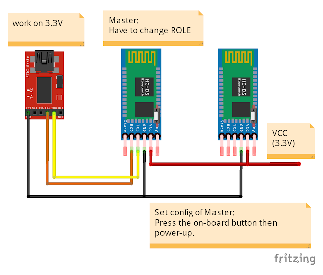
Config HC-05(s) as paired Master and Slave

This post show how to set a HC-05 as Master, and bind to another Slave HC-05. By default, HC-05 is set as Slave (ROLE=0), UART=9600,0,0 and PSWD="1,2,3,4", what we have to do on Slave is to copy the ADDR used to bind in Master. In Master side, what we have to do is set as Master (ROLE=1), make sure same UART and PSWD,  BIND to Slave's ADDR, and set CMODE=0, such that the Master will connect the assigned Slave only. Once set, the Master/Slave pair will auto-connect when power-up in range.


In my setup, a FTDI USB-to-Serial adapter is used to check/set the HC-05(s), Arduino Software's Serial Monitor is used to enter AT command to HC-05, all FTDI adapter, both HC-05 are set working on 3.3V.


Check the config of Slave HC-05:

Connection:
FTDI Tx - Slave HC-05 Rx
FTDI Rx - Slave HC-05 Tx
FTDI GND - Slave HC-05 GND

Conenct USB to FTDI, and open  Arduino Serial Monitor, set baud rate to 38400, "Both NL & CR".

Press the on-board button of Slave HC-05 and apply power to Slave HC-05.


Make sure ROLE=0, UART=9600,0,0, PSWD="1234" by entering AT Commands:
AT+ROLE?
AT+UART?
AT+PSWD?

Copy the ADDR:
AT+ADDR?

In my case, ADDR is 2014:12:20016

Power-off and disconnect the Slave HC-05.


Set the config of Master HC-05:

Connection:
FTDI Tx - Master HC-05 Rx
FTDI Rx - Master HC-05 Tx
FTDI GND - Master HC-05 GND

Press the on-board button of  Master HC-05 and apply power to Master HC-05.


Make suew UART and PSWD match with Slave side:
AT+UART?
AT+PSWD?

Change ROLE to Master
AT+ROLE=1

Bind to the ADDR of Slave. In my case Slave's ADDR is 2014:12:20016, replace ':' by ',', enter:
AT+BIND=2014,12,20016

And set CMODE=0:
AT+CMODE=0

Power-off the Master HC-05.


Auto connect:

Keep FTDI connect to Master HC-05. Connect TXD and RXD of Slave HC-05 together, to echo the received data back to sender.

Power-up both Master and Slave HC-05, don't press the on-board button.

Change baud rate of Arduino Serial Monitor to 9600 (match with the UART in HC-05), keep using "Both NL & CR".


Notice the blinking pattern of the on-board LED of HC-05(s), they will auto-connect once power-up.

Enter anything in Arduino Serial Monitor, it will be send to Master HC-05, and send to paired Slave HC-05 and echo back via Bluetooth,


Reference:
Elastic Sheep - Serial Bluetooth module – Master/Slave connection
iteadstudio - Serial Port Bluetooth Module (Master/Slave) : HC-05
AT Command mode of HC-05

Test the Gyro of Arduino/Genuino 101


To try the Gyro function of Arduino/Genuino 101 board, open the CurieIMU Gyro example:
File > Examples > CurieIMU > Gyro


Gyro.ino
/*
   Copyright (c) 2015 Intel Corporation.  All rights reserved.

   This library is free software; you can redistribute it and/or
   modify it under the terms of the GNU Lesser General Public
   License as published by the Free Software Foundation; either
   version 2.1 of the License, or (at your option) any later version.

   This library is distributed in the hope that it will be useful,
   but WITHOUT ANY WARRANTY; without even the implied warranty of
   MERCHANTABILITY or FITNESS FOR A PARTICULAR PURPOSE.  See the GNU
   Lesser General Public License for more details.

   You should have received a copy of the GNU Lesser General Public
   License along with this library; if not, write to the Free Software
   Foundation, Inc., 51 Franklin Street, Fifth Floor, Boston, MA  02110-1301  USA

*/

/*
   This sketch example demonstrates how the BMI160 on the
   Intel(R) Curie(TM) module can be used to read gyroscope data
*/

#include "CurieIMU.h"

void setup() {
  Serial.begin(9600); // initialize Serial communication
  while (!Serial);    // wait for the serial port to open

  // initialize device
  Serial.println("Initializing IMU device...");
  CurieIMU.begin();

  // Set the accelerometer range to 250 degrees/second
  CurieIMU.setGyroRange(250);
}

void loop() {
  int gxRaw, gyRaw, gzRaw;         // raw gyro values
  float gx, gy, gz;

  // read raw gyro measurements from device
  CurieIMU.readGyro(gxRaw, gyRaw, gzRaw);

  // convert the raw gyro data to degrees/second
  gx = convertRawGyro(gxRaw);
  gy = convertRawGyro(gyRaw);
  gz = convertRawGyro(gzRaw);

  // display tab-separated gyro x/y/z values
  Serial.print("g:\t");
  Serial.print(gx);
  Serial.print("\t");
  Serial.print(gy);
  Serial.print("\t");
  Serial.print(gz);
  Serial.println();

  // wait 5 seconds
  delay(5000);
}

float convertRawGyro(int gRaw) {
  // since we are using 250 degrees/seconds range
  // -250 maps to a raw value of -32768
  // +250 maps to a raw value of 32767
  
  float g = (gRaw * 250.0) / 32768.0;

  return g;
}


Arduino/Genuino 101 CurieIMU Gyro
With this tutorial you learn to read the gyroscope raw values and convert them into an angular velocity around each of the three axes. This information is useful to measure rotational movement around the three axes, something that acceleration can't measure if the movement is continuous.
~ reference: https://www.arduino.cc/en/Tutorial/Genuino101CurieIMUGyro


Wednesday, April 13, 2016

Arduino/Genuino 101 example to read button and turn ON/OFF LED


Simple example of Arduino/Genuino 101, to read button (on pin 6) and control LED (on pin 7) accodingly.

Connection:

_101_button_led.ino
/*
 * Arduino/Genuino 101 example
 * to read button and turn ON/OFF LED accordingly
 */

int LED = 7;
int BTN = 6;

void setup() {
  pinMode(LED, OUTPUT);
  pinMode(BTN, INPUT_PULLUP);

  //indicate program start
  pinMode(13, OUTPUT);
  digitalWrite(13, LOW);
  delay(200);
  digitalWrite(13, HIGH);
  delay(1000);
  digitalWrite(13, LOW);
}

void loop() {
  digitalWrite(LED, !digitalRead(BTN));
  delay(100);
}


Install Arduino/Genuino 101 to Arduino Software and run Blink on Genuino 101


To install Arduino/Genuino 101 to Arduino Software, click Tools > Board: > Boards Manager and install "Intel Curie Boards by Intel".


This video show how to, and open example of Blink to run on Genuino 101.


Genuino 101 Open Box, and examples

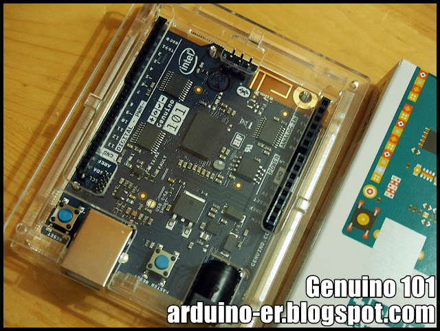
The Genuino 101 board have the same size of Arduino UNO, and fit the case for UNO, except the MASTER RESET button cannot be accessed if the top cover closed.


Fritzing part of Arduino/Genuino 101 can be download HERE.


More:
- Install Arduino/Genuino 101 to Arduino Software and run Blink on Genuino 101
Arduino/Genuino 101 example to read button and turn ON/OFF LED
Test the Gyro of Arduino/Genuino 101
Arduino/Genuino 101 CurieIMU Orientation Visualiser

ESP12E Motor Shield - NodeMCU + Motor Driver Expansion Board

Come with NodeMCU/ESP-12E and Motor Driver Expansion Board:


info: http://nodemcu-motor.doit.am/ (Chinese)

Monday, April 11, 2016

Android BluetoothChat connect to Arduino Uno + HC-05

Last example show "Android BluetoothChat example link with HC-05 Bluetooth", to connect to PC via FTDI adapter. Here is another example - Arduino UNO + HC-05 to echo received data back to the sender.

For my on-hand HC-05 sample, it set as slave role and 9600, 0, 0, PIN="1234" by default. So it can be used in this example without any extra setting.


Connection between UNO and HC-05
HC-05 Rx - Uno Tx (1)
HC-05 Tx - Uno Rx (0)
HC-05 GND - Uno GND
HC-05 VCC - Uno 5V
(My HC-05 marked "Power: 3.6V-6V", refer here, make sure your HC-05 can work on 5V.)

Uno_Serial_echo.ino
/*
Arduino Uno + HC-05 (Bluetooth) - echo bluetooth data

Serial (Tx/Rx) communicate to HC-05
HC-05 Rx - Uno Tx (1)
HC-05 Tx - Uno Rx (0)
HC-05 GND - Uno GND
HC-05 VCC - Uno 5V

*/

void setup()
{
  delay(1000);
  Serial.begin(9600);
}

void loop()
{
  while(Serial.available())
  {
    char data = Serial.read();
    Serial.write(data);
  }
}

This video show how Android BluetoothChat example link with Arduino UNO + HC-05. For the Android BluetoothChat example, refer last post.


Related:
Connect Arduino Due with HC-06 (Bluetooth Module)


Thursday, April 7, 2016

Android BluetoothChat example link with HC-05 Bluetooth

This example show to import and modify Android BluetoothChat example, to link with low-cost Bluetooth HC-05.

reference:
First test HC-05 Bluetooth Module
AT Command mode of HC-05

We need a FTDI USB-to-Serial adapter to connect PC/USB and HC-05 Bluetooth, and use Arduino IDE's Serial Monitor as terminal, to talk with Android running modified BluetoothChat example.


This video show how to import BluetoothChat example in Android Studio, and edit BluetoothChatService.java to change MY_UUID_SECURE to UUID.fromString("00001101-0000-1000-8000-00805F9B34FB").

~ reference http://developer.android.com/reference/android/bluetooth/BluetoothDevice.htmlIf you are connecting to a Bluetooth serial board then try using the well-known SPP UUID 00001101-0000-1000-8000-00805F9B34FB.


This video show how it run on Android device, and talk to PC running Arduino IDE's Serial Monitor, via FTDI + HC-05.

In my on-hand HC-05 sample, it set as slave role and 9600, 0, 0, PIN="1234" by default, I have not change any setting.


Cross-post with Android-er

Next:
Android BluetoothChat connect to Arduino Uno + HC-05

Wednesday, April 6, 2016

AT Command mode of HC-05

HC-05 Bluetooth Module support both Master and Slave roles. We can set it in AT Command mode. There are a number of variant of HC-05, and different ways to enter AT Command mode. For my samples, there is a button on the lower-right, above EN pin. It's used to enter AT Command mode when power-on.


This video show how to connect PC to HC-05, via FTDI USB-to-Serial adapter, power-on HC-05 in AT Command mode, and enter AT Command using Arduino Serial Monitor to check setting of HC-05.


Please notice both FTDI USB-to-Serial adapter and HC-05 have to work on the same voltage, both 3.3V or both 5V.

- Connect FTDI and HC-05
FTDI Tx - HC-05 Rx
FTDI Rx - HC-05 Tx
FTDI GND - HC-05 GND
(no power apply to HC-05 now)

- Connect FTDI to PC using USB cable.
- You can check the COM port connect to FTDI in Deviec Manager.
- Start Arduino IDE, and run Tools > Serial Monitor.
- Set baud rate 38400 and select "both NL & CR".

- Press the on-board button of HC-05.
- Apply power to HC-05.
- The on-board LED of HC-05 will blink slowly.
- Now it's in AT Command mode.

- You can type AT command in Arduino Serial Monitor to check or set the setting of HC-05.

Some useful command:
AT : return OK if connect correctly.
AT+NAME : get/set name of the device. Nothing return in my sample.
AT+ADDR : display default address
AT+VERSION : display firmware version
AT+UART : get/set serial communication setting; such as baud, number of stop bit, and parity.
AT+ROLE: get/see role of bt module(1=master/0=slave)
AT+RESET : Reset and exit AT mode
AT+ORGL : Restore factory settings
AT+PSWD: get/set default PIN

reference:
iteadstudio: Serial Port Bluetooth Module (Master/Slave) : HC-05
- HC-03/05 Embedded Bluetooth Serial Communication Module
AT command set


Tuesday, April 5, 2016

First test HC-05 Bluetooth Module


This video show my first test of HC-05 Bluetooth Module. Connect a FTDI USB-to-Serial adapter to HC-05. And try communication between Arduino Serial Monitor > FTDI > HC-05 and PC (running Windows 10) Bluetooth (PuTTY).


By default, HC-05 work as slave, and have name and pin of "HC-05" and "1234".

Connection between FTDI and HC-05
FTDI Tx - HC-05 Rx
FTDI Rx - HC-05 Tx
FTDI GND - HC-05 GND
HC-05 VCC - separated 3.3V


Next:
AT Command mode of HC-05
Android BluetoothChat example link with HC-05 Bluetooth
Android BluetoothChat connect to Arduino Uno + HC-05
Config HC-05(s) as paired Master and Slave

Monday, April 4, 2016

NodeMCU act as WiFi client to update dweet.io


dweet.io is simple publishing and subscribing for machines, sensors, devices, robots, and gadgets (we just call them things). We call published messages ‘dweets’. It’s helpful to think of dweet.io as a Twitter for things, in fact.

I have a old example to show how to "Arduino Uno + Ethernet Shield send data to dweet.io and freeboard.io". It's a NodeMCU (with ESP8266 core for Arduino) version to update dweet.io.

You can visit following link on web browser to update dweet.io manually to test your url:
www.dweet.io/dweet/for/test_NodeMCU?A0=123

And check your thing at:
http://dweet.io/follow/test_NodeMCU

where testNodeMCU is the id of your thing in dweet.io, 123 is the value to update.

This code run on NodeMCU (suppose other standalone ESP8266 also), to connect to WiFi as client, read analog input from A0, and update dweet.io. (It's modified from Examples > ESP8266WiFi > WiFiClient,)


Connect analog input to A0, connection refer to last post "NodeMCU to read analog input, A0".

NodeMCU_WiFiClient_dweetio.ino
/*
 * reference: Examples > ESP8266WiFi > WiFiClient 
 */

#include <ESP8266WiFi.h>
const int AnalogIn  = A0;

const char* ssid     = "myssid";
const char* password = "password";

const char* host = "www.dweet.io";
const char* thing  = "test_NodeMCU";
const char* thing_content = "A0";

void setup() {
  Serial.begin(115200);
  delay(10);

  // We start by connecting to a WiFi network

  Serial.println();
  Serial.println();
  Serial.print("Connecting to ");
  Serial.println(ssid);
  
  WiFi.begin(ssid, password);
  
  while (WiFi.status() != WL_CONNECTED) {
    delay(500);
    Serial.print(".");
  }

  Serial.println("");
  Serial.println("WiFi connected");  
  Serial.println("IP address: ");
  Serial.println(WiFi.localIP());
}

int value = 0;

void loop() {
  delay(1000);
  value = analogRead(AnalogIn);

  Serial.print("connecting to ");
  Serial.println(host);
  
  // Use WiFiClient class to create TCP connections
  WiFiClient client;
  const int httpPort = 80;
  if (!client.connect(host, httpPort)) {
    Serial.println("connection failed");
    return;
  }
  
  // We now create a URI for the request
  String url = "/dweet/for/";
  url += thing;
  url += "?";
  url += thing_content;
  url += "=";
  url += value;
  
  Serial.print("Requesting URL: ");
  Serial.println(url);
  
  // This will send the request to the server
  client.print(String("GET ") + url + " HTTP/1.1\r\n" +
               "Host: " + host + "\r\n" + 
               "Connection: close\r\n\r\n");
  int timeout = millis() + 5000;
  while (client.available() == 0) {
    if (timeout - millis() < 0) {
      Serial.println(">>> Client Timeout !");
      client.stop();
      return;
    }
  }
  
  // Read all the lines of the reply from server and print them to Serial
  while(client.available()){
    String line = client.readStringUntil('\r');
    Serial.print(line);
  }
  
  Serial.println();
  Serial.println("closing connection");
}


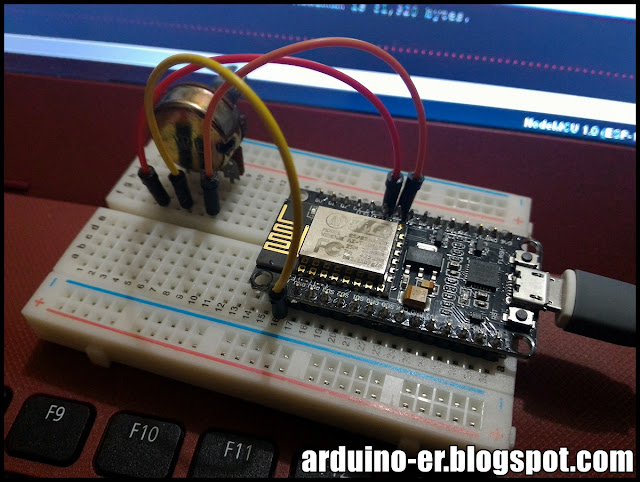
NodeMCU to read analog input, A0.


Last post introduced "Serial Plotter in Arduino IDE" with Arduino Uno example to read analog input and println to Serial Port, to display on Arduino Software's Serial Plotter. The example can direct re-compile and run target NodeMCU/ESP8266.


remark: Fritzing part of NodeMCU can be found HERE.

Example code, same as in last post.
const int AnalogIn  = A0;

int readingIn = 0;

void setup() {
  Serial.begin(9600);
}

void loop() {
  readingIn = analogRead(AnalogIn);
  Serial.println(readingIn);
}


Serial Plotter in Arduino IDE


Start from ARDUINO 1.6.6 (2015.11.03), Serial Plotter is added under Tools > Serial Plotter.

This video show how to use it.


Example running on Arduino Uno in the video, read Analog Input from A0, and println to serial port.
const int AnalogIn  = A0;

int readingIn = 0;

void setup() {
  Serial.begin(9600);
}

void loop() {
  readingIn = analogRead(AnalogIn);
  Serial.println(readingIn);
}

remark: This code can run on NodeMCU also.


Sunday, April 3, 2016

Arduino Day and Genuino Day 2016 - Message from Arduino co-founders

Massimo Banzi, Tom Igoe and David Mellis are in Berkeley to celebrate Arduino Day and Genuino Day. Here's their message to all the community of organizers, participants and all Arduino fans!
http://day.arduino.cc

Arduino release new web site create.arduino.cc

Arduino release new web site create.arduino.cc, the Arduino platform that will provide the community with a more modern and flexible tool to write code, a more integrated way of accessing content and learning while doing.


know more: Arduino Blog - WELCOME ARDUINO PROJECT HUB AND ARDUINO IOT!