Showing posts with label I2C SSD1306 OLED. Show all posts

Thursday, December 31, 2020

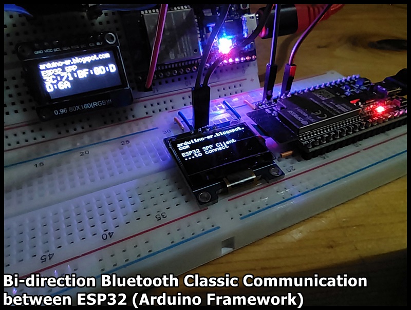
Bi-direction Bluetooth Classic comm. between ESP32 (Arduino framework)

Last post show my exercise of "ESP-32S as Bluetooth classic Server, bi-direction communication with Raspberry Pi/Python". Here is the ESP32 implementation for the Client side, to connect to the ESP32 server in last post.

NodeMCU ESP-32S act as a server (in last post):
It echo what received from bluetooth back to sender, and display on SPI ST7735 display.

ESP32-DevKitC-V4 as client (this post):
Connect to server, forward data from serial,  to Bluetooth. Display data from Bluetooth on I2C SSD1306 OLED display.

The code start from ESP32 example of SerialToSerialBTM. But I found that the code SerialBT.connect() always return "true", and prompt "Connected Succesfully!", no matter the device name and MAC address, even no server exist. 

To solve it, I implement my bluetooth callback function to double check if ESP_SPP_OPEN_EVT raised. I don't know is it a long time solution, anyway it work in this exercise.

SPPClient_ESP32_ssd1306_20201231b.ino
/*
 * SPP Client on ESP32
 * Display on  SSD1306
 */

#include "ssd1306.h"
#include "ssd1306_console.h"
#include "BluetoothSerial.h"

Ssd1306Console  console;

BluetoothSerial SerialBT;

String ServerMACadd = "3C:71:BF:0D:DD:6A";
uint8_t ServerMAC[6]  = {0x3C, 0x71, 0xBF, 0x0D, 0xDD, 0x6A};
String ServerName = "ESP32_SPP";
char *pin = "1234"; //<- standard pin would be provided by default
bool connected;
bool isSppOpened = false;

/*
.arduino15/packages/esp32/hardware/esp32/1.0.4/libraries/
BluetoothSerial/src/BluetoothSerial.cpp

 */

void btCallback(esp_spp_cb_event_t event, esp_spp_cb_param_t *param){
  
  switch (event)
    {
    case ESP_SPP_INIT_EVT:
        Serial.println("ESP_SPP_INIT_EVT");
        break;

    case ESP_SPP_SRV_OPEN_EVT://Server connection open
        Serial.println("ESP_SPP_SRV_OPEN_EVT");
        break;

    case ESP_SPP_CLOSE_EVT://Client connection closed
        Serial.println("ESP_SPP_CLOSE_EVT");
        isSppOpened = false;
        break;

    case ESP_SPP_CONG_EVT://connection congestion status changed
        Serial.println("ESP_SPP_CONG_EVT");
        break;

    case ESP_SPP_WRITE_EVT://write operation completed
        Serial.println("ESP_SPP_WRITE_EVT");
        break;

    case ESP_SPP_DATA_IND_EVT://connection received data
        Serial.println("ESP_SPP_DATA_IND_EVT");
        break;

    case ESP_SPP_DISCOVERY_COMP_EVT://discovery complete
        Serial.println("ESP_SPP_DISCOVERY_COMP_EVT");
        break;

    case ESP_SPP_OPEN_EVT://Client connection open
        Serial.println("ESP_SPP_OPEN_EVT");
        isSppOpened = true;
        break;

    case ESP_SPP_START_EVT://server started
        Serial.println("ESP_SPP_START_EVT");
        break;

    case ESP_SPP_CL_INIT_EVT://client initiated a connection
        Serial.println("ESP_SPP_CL_INIT_EVT");
        break;

    default:
        Serial.println("unknown event!");
        break;
    }
}

static void startupScreen()
{
    ssd1306_setFixedFont(ssd1306xled_font6x8);
    ssd1306_clearScreen();
    ssd1306_printFixed(0, 0, "arduiino-er.blogspot.com", STYLE_BOLD);
    ssd1306_printFixed(0, 24, "ESP32 SPP Client", STYLE_NORMAL);
}

void setup()
{
    Serial.begin(115200);
    Serial.println("\n------ begin ----------------\n");
    
    ssd1306_128x64_i2c_init();
    ssd1306_clearScreen();
    startupScreen();
    delay(500);

    Serial.println("- to connect -");
    ssd1306_printFixed(0, 32, "...to connect", STYLE_NORMAL);
    
    SerialBT.begin("ESP32_Client", true);
    SerialBT.register_callback(btCallback);
    //connected = SerialBT.connect(ServerName);
    connected = SerialBT.connect(ServerMAC);

    /*
     * In my trial, 
     * SerialBT.connect() always return  true, even no server exist.
     * To solve it, I implemented bluetooth event callback function,
     * double varify if ESP_SPP_OPEN_EVT raised.
     */
    
    if(connected) {
      Serial.println("SerialBT.connect() == true");
    } else {
      Serial.println("Failed to connect! Reset to re-try");
      Serial.println("SerialBT.connect() == false");
      ssd1306_printFixed(0, 32, 
          "Failed to connect! Reset to re-try", STYLE_NORMAL);
      while(true){
      }
    }

    //may be there are some delay to call callback function,
    //delay before check
    delay(500);
    if(isSppOpened == false){
      Serial.println("isSppOpened == false");
      Serial.println("Reset to re-try");
      ssd1306_printFixed(0, 32, 
          "SPP_OPEN not raised! Reset to re-try", STYLE_NORMAL);
      while(true){
      }
    }
    
    Serial.println("isSppOpened == true");
    Serial.println("CONNECTED");

    ssd1306_clearScreen();
    ssd1306_setFixedFont(ssd1306xled_font6x8);
    console.println("CONNECTED:");
}

void loop()
{
    if(!isSppOpened){
      Serial.println("isSppOpened == false : DISCONNECTED");
      Serial.println("Reset to re-connect");
      console.println("DISCONNECTED");
      console.println("Reset to re-connect");
      while(true){
      }
    }
    if (Serial.available()) {
      SerialBT.write(Serial.read());
    }
    if (SerialBT.available()) {
      char c = SerialBT.read();
      //Serial.write(c);
      console.print(c);
    }
    delay(20);
}

For the setup of SPI ST7735 IPS used on server side, refer to the post "ESP32 display with 0.96" 80x160 SPI ST7735 IPS Display, using TFT_eSPI lib".

For the setup of I2C SSD1306 OLED used on client side, refer to the post "I2C SSD1306 OLED@ESP32 (ESP32-DevKitC-V4), using SSD1306 lib".

Friday, December 25, 2020

ESP32 receive Bluetooth Classic command from Raspberry Pi/Python, to control Servos.

In my previous posts, I show simple examples of ESP32 Bluetooth Classic serial exampleServo Motor Control and I2C SSD1306 OLED. In this exercise, group three altogether run on ESP32-DevKitC-V4, receive single character command from Raspberry Pi/Python via Bluetooth Classic, control Servo Motors, and display position on 0.96" 128x64 I2C SSD1306 OLED.

Connection:

BTServoServer_20201226.ino

// BTServoServer

#include "BluetoothSerial.h"
#include "esp_bt_device.h"
#include "ssd1306.h"
#include <ESP32Servo.h>

#if !defined(CONFIG_BT_ENABLED) || !defined(CONFIG_BLUEDROID_ENABLED)
#error Bluetooth is not enabled! Please run `make menuconfig` to and enable it
#endif

BluetoothSerial SerialBT;
Servo myservoX;  // create servo objects to control a servo
Servo myservoY;
int servoPinX = 18;
int servoPinY = 19;

#define CMD_ORG 'O'
#define CMD_XDEC 'A'
#define CMD_XDEC10 'B'
#define CMD_XINC 'C'
#define CMD_XINC10 'D'
#define CMD_YDEC 'E'
#define CMD_YDEC10 'F'
#define CMD_YINC 'G'
#define CMD_YINC10 'H'

int x = 0;
int y = 0;

void printDeviceAddress() {
 
  const uint8_t* point = esp_bt_dev_get_address();
 
  for (int i = 0; i < 6; i++) {
 
    char str[3];
 
    sprintf(str, "%02X", (int)point[i]);
    Serial.print(str);
 
    if (i < 5){
      Serial.print(":");
    }
 
  }
}

void setup() {
  Serial.begin(115200);
  Serial.println("\n---Start---");
  SerialBT.begin("ESP32test"); //Bluetooth device name
  
  Serial.println("The device started, now you can pair it with bluetooth!");
  Serial.println("Device Name: ESP32test");
  Serial.print("BT MAC: ");
  printDeviceAddress();
  Serial.println();

  ssd1306_setFixedFont(ssd1306xled_font6x8);
  ssd1306_128x64_i2c_init();
  ssd1306_clearScreen();
  ssd1306_printFixed(0,  8, "BTServoServer", STYLE_BOLD);
  ssd1306_printFixed(0,  40, "arduino-er.blogspot.com", STYLE_BOLD);

  // Allow allocation of all timers
  ESP32PWM::allocateTimer(0);
  ESP32PWM::allocateTimer(1);
  ESP32PWM::allocateTimer(2);
  ESP32PWM::allocateTimer(3);
  myservoX.setPeriodHertz(50);    // standard 50 hz servo
  myservoX.attach(servoPinX, 500, 2500); // attaches the servo on pin 18 to the servo object
  myservoY.setPeriodHertz(50);    // standard 50 hz servo
  myservoY.attach(servoPinY, 500, 2500);

  myservoX.write(90);
  myservoY.write(90);
}

void loop() {
  if (SerialBT.available()) {
    char cmd = SerialBT.read();
    switch(cmd) {
      case CMD_ORG:
            x = 0;
            y = 0; 
            break;
      case CMD_XDEC:
            x--;
            break;
      case CMD_XDEC10:
            x = x-10;
            break;
      case CMD_XINC:
            x++;
            break;
      case CMD_XINC10:
            x = x+10;
            break;
      case CMD_YDEC:
            y--;
            break;
      case CMD_YDEC10:
            y = y-10;
            break;
      case CMD_YINC:
            y++;
            break;
      case CMD_YINC10:
            y = y+10;
            break;
      default:
            Serial.println("unknown command!");
            break;
    }

    if(x < -90)
      x = -90;
    if(x > 90)
      x = 90;
    if(y < -90)
      y = -90;
    if(y > 90)
      y = 90;

    String s = String(x, DEC) + " : " + String(y, DEC) + "    ";
    const char* c;
    c = s.c_str();
    Serial.println(s);
    ssd1306_printFixed(0, 25, c, STYLE_NORMAL);

    myservoX.write(x + 90);
    myservoY.write(y + 90);
    delay(200);             // wait for the servo to get there
  }
  delay(20);
}


Python code in Raspberry Pi side, refer to my another blog's post: Hello Raspberry Pi - Raspberry Pi/Python remote control ESP32/Servos via Bluetooth Classic

Next:

Thursday, December 24, 2020

I2C SSD1306 OLED@ESP32 (ESP32-DevKitC-V4), using SSD1306 lib.

ESP32 (ESP32-DevKitC-V4) run in Arduino framework, to display on 0.96" 128x64/0.91"128x32 OLED with I2C SSD1306 driver, using SSD1306 library.

Install Library:

Search and install ssd1306 library (by Alexey Dynda) via Arduino IDE library manager.

Connection:

ESP32			I2C SSD1306 OLED
(ESP32-DevKitC-V4)
====================================
3V3			VCC
GND			GND
IO22			SCL
IO21			SDA

Example:

Open File > Examples > ssd1306 > demos > ssd1306_demo

Save, verify and upload.


Related:


Monday, May 18, 2020

ESP8266 (NodeMCU) - Get current weather data from OpenWeatherMap, using ArduinoJson

This exercise run on ESP8266 (NodeMCU), to get current weather data from OpenWeatherMap.


OpenWeatherMap provide easy-to-work weather APIs. Before you can use the APIs, you have to sign-up your account with email, for free.

After sign-up, and email varified, you can get various weather info using APIs with your api key. For example to get current weather:
http://api.openweathermap.org/data/2.5/weather?q=London,uk&APPID=<your key here>

This example with your api key will be sent you in the confirm email. You can paste it in browser, to receive the response in JSON form.


Copy the returned JSON to the input box in ArduinoJson Assistant, it will return you the Memory pool size, and example to Parsing program.


ArduinoJson is a simple and efficient JSON library for embedded C++. Support various platforms of Arduino framework. Already included in Platform IO.


For connection between ESP8266 and the I2C OLED, refer last post "ESP8266 (NodeMCU/ESP8266 DevKitC) + SSD1306 I2C OLED, Platform IO".

Here is my exercise run on ESP8266 (NodeMCU), to get current weather data from OpenWeatherMap, using libraries ESP8266WiFi, ESP8266HTTPClient, ArduinoJson, and display on I2C OLED using library ESP8266_SSD1306.

#include <Arduino.h>
#include "SSD1306Wire.h"
#include <ESP8266WiFi.h>
#include <ESP8266HTTPClient.h>
#include <ArduinoJson.h>

const char* ssid = "station";
const char* password = "password";

const String api_1 = "http://api.openweathermap.org/data/2.5/weather?q=";
const String qLocation = "London,uk";
const String api_2 = "&units=metric"; //request return temp in celsius
const String api_3 = "&APPID=";
const String api_key = "09816ba66b72ec172f3b8e1982c962ff";  //your api key
const String rqs = api_1 + qLocation + api_2 + api_3 + api_key;

SSD1306Wire  display(0x3c, D3, D5);

//Visit ArduinoJson Assistant (https://arduinojson.org/v6/assistant/)
//To get Memory pool size
StaticJsonDocument<800> doc;

void sendRqs(){

  HTTPClient http;
  http.begin(rqs);
  int httpCode = http.GET();

  if (httpCode > 0) { 

    String response = http.getString();
    //display.clear();
    //display.drawString(0, 0, "response:");
    //display.drawString(0, 10, response);
    //display.display();

    Serial.println(response);

    // Deserialize the JSON document
    DeserializationError error = deserializeJson(doc, response);

    // Test if parsing succeeds.
    if (error) {

      String errorStr = error.c_str();

      display.clear();
      display.drawString(0, 0, "deserializeJson() error:");
      display.drawString(0, 10, errorStr);
      display.display();

      Serial.println(errorStr);

      delay(10000);
    }else{
      Serial.println("deserializeJson() no error.");

      //--- Copy from ArduinoJson Assistant
      float coord_lon = doc["coord"]["lon"];
      float coord_lat = doc["coord"]["lat"];

      JsonObject weather_0 = doc["weather"][0];
      int weather_0_id = weather_0["id"];
      const char* weather_0_main = weather_0["main"];
      const char* weather_0_description = weather_0["description"];
      const char* weather_0_icon = weather_0["icon"];

      const char* base = doc["base"];

      JsonObject main = doc["main"];
      float main_temp = main["temp"];
      float main_feels_like = main["feels_like"];
      float main_temp_min = main["temp_min"];
      float main_temp_max = main["temp_max"];
      int main_pressure = main["pressure"];
      int main_humidity = main["humidity"];

      int visibility = doc["visibility"];

      float wind_speed = doc["wind"]["speed"];
      int wind_deg = doc["wind"]["deg"];

      int clouds_all = doc["clouds"]["all"];

      long dt = doc["dt"];

      JsonObject sys = doc["sys"];
      int sys_type = sys["type"];
      int sys_id = sys["id"];
      const char* sys_country = sys["country"];
      long sys_sunrise = sys["sunrise"];
      long sys_sunset = sys["sunset"];

      int timezone = doc["timezone"];
      long id = doc["id"];
      const char* name = doc["name"];
      int cod = doc["cod"];

      //--- End of ArduinoJson Assistant ---

      // Print values.
      Serial.println("temp_min: " + String(main_temp_min));
      Serial.println("temp_max: " + String(main_temp_max));

      display.clear();
      display.drawString(0, 0, name);
      display.drawString(0, 10, "temp_min: " + String(main_temp_min));
      display.drawString(0, 20, "temp_max: " + String(main_temp_max));

      display.display();
    }

  }else{
    display.clear();
    display.drawString(0, 0, "http.GET() == 0");
    display.display();
    Serial.println("http.GET() == 0");
  }
  
  http.end();   //Close connection

}

void setup() {

  Serial.begin(9600);

  display.init();
  display.setContrast(255);
  display.clear();

  display.drawString(0, 0, "ESP32/OLED");
  display.display();

  WiFi.begin(ssid, password);
  display.drawString(0, 10, "Connecting...");
  display.display();
  while (WiFi.status() != WL_CONNECTED) {
    delay(800);
  }
}

void loop() {
  display.clear();
  if (WiFi.status() == WL_CONNECTED) {
    display.drawString(0, 0, "CONNECTED");
    display.display();

    sendRqs();

  }else{
    display.drawString(0, 0, "NOT CONNECTED");
    display.display();
  }
  
  Serial.println("DONE");
  delay(10000);
}


Saturday, May 16, 2020

ESP8266 (NodeMCU/ESP8266 DevKitC) + SSD1306 I2C OLED, Platform IO.

NodeMCU + SSD1306 I2C OLED

Steps to new a PlatformIO project, for NodeMCU board of Arduino framework, using library and example of ESP8266_SSD1306, to display on I2C SSD1306 OLED display. Tested on Windows 10/VirtualBox.


- Connect NodeMCU to I2C SSD1306 OLED:


- Refer to previous post to Install VS Code/PlatformIO IDE on Ubuntu 20.04.

- Make sure the library ESP8266_SSD1306 is installed.


- Create a new project using NodeMCU board and Arduino framework.

- Open PlatformIO - Libraries page, copy example of ESP8266_SSD1306 library to our main.c.

- Edit platformio.ini to specify upload_port.

- Finally, Build and Upload. Done.


Espressif ESP8266 DevKitC + SSD1306 I2C OLED

Then I tried to test it on Espressif ESP8266 DevKitC, with module ESP-WROOM-02D.

It's found from ESP-WROOM-02D/02U Datasheet, I2C is assigned to IO14 (SCL), IO2 (SDA).


So I re-connect accordingly.

ESP8266 DevKitC <-> I2C SSD1306 OLED
3V3 - VCC
GND - GND
IO2 - SDA
IO14 - SCL

And edit main.c, change the code:

from:
SSD1306Wire  display(0x3c, D3, D5);

to:
SSD1306Wire  display(0x3c, 2, 14);


Re-build, and upload...done.


Next:
ESP8266 (NodeMCU) - Get current weather data from OpenWeatherMap, using ArduinoJson


Saturday, April 6, 2019

ESP32 + OLED Module

It's a ESP32 module with integrated OLED.


It pre-load with a demo program. In first power-up, the OLED show a all ON screen and a welcome message alternatively.


Make the OLED work:

First of all, I install both ESP32 and ESP8266 on Arduino IDE.

The first thing I want to do is make the OLED work. But it's only limit info from the seller, only mention that it's WEMOS LoLin32, without any about the OLED. So I have to search, guess and try.

After searched in some Chinese website, I guess that the OLED driver for this module should be SSD1306, with I2C interface. and the I2C pin should be 5 and 4 for ESP32.

Then I have to identify the I2C address. I found a i2c_scanner example from Arduino Playground. Have to modify the code Wire.begin() to Wire.begin(5,4) for ESP32.

The full code is here:
// Copy from Arduino Playground - i2c_scanner
// https://playground.arduino.cc/Main/I2cScanner/
// --------------------------------------
// i2c_scanner
//
// Version 1
//    This program (or code that looks like it)
//    can be found in many places.
//    For example on the Arduino.cc forum.
//    The original author is not know.
// Version 2, Juni 2012, Using Arduino 1.0.1
//     Adapted to be as simple as possible by Arduino.cc user Krodal
// Version 3, Feb 26  2013
//    V3 by louarnold
// Version 4, March 3, 2013, Using Arduino 1.0.3
//    by Arduino.cc user Krodal.
//    Changes by louarnold removed.
//    Scanning addresses changed from 0...127 to 1...119,
//    according to the i2c scanner by Nick Gammon
//    https://www.gammon.com.au/forum/?id=10896
// Version 5, March 28, 2013
//    As version 4, but address scans now to 127.
//    A sensor seems to use address 120.
// Version 6, November 27, 2015.
//    Added waiting for the Leonardo serial communication.
// 
//
// This sketch tests the standard 7-bit addresses
// Devices with higher bit address might not be seen properly.
//

#include <Wire.h>


void setup()
{
  Wire.begin(5,4);  //Modifed for ESP32

  Serial.begin(9600);
  while (!Serial);             // Leonardo: wait for serial monitor
  Serial.println("\nI2C Scanner");
}


void loop()
{
  byte error, address;
  int nDevices;

  Serial.println("Scanning...");

  nDevices = 0;
  for(address = 1; address < 127; address++ ) 
  {
    // The i2c_scanner uses the return value of
    // the Write.endTransmisstion to see if
    // a device did acknowledge to the address.
    Wire.beginTransmission(address);
    error = Wire.endTransmission();

    if (error == 0)
    {
      Serial.print("I2C device found at address 0x");
      if (address<16) 
        Serial.print("0");
      Serial.print(address,HEX);
      Serial.println("  !");

      nDevices++;
    }
    else if (error==4) 
    {
      Serial.print("Unknown error at address 0x");
      if (address<16) 
        Serial.print("0");
      Serial.println(address,HEX);
    }    
  }
  if (nDevices == 0)
    Serial.println("No I2C devices found\n");
  else
    Serial.println("done\n");

  delay(5000);           // wait 5 seconds for next scan
}

Remember to select board of "WEMOS LoLin32" before download.

The I2C address is 0x3C.

Then I tried to find any library suitable in Arduino IDE, and found "ESP8266 and ESP32 Oled Driver for SSD1306 by Daniel Eichhorn, Fabrice Weinberg".

Luckily it work as expect.

Tried to load the example of SSD1306SimpleDemo, simple modify the code
SSD1306Wire  display(0x3c, D3, D5);

to
SSD1306Wire  display(0x3c, 5, 4);

to make it work for this module.


This video show how to:


A minimum exercise to display simple text.

/*
 * A ESP32/OLED exercise to display simple text
 * Board:
 * esp32 by Espressif Systems version 1.0.4
 * OLED library:
 * ESP8266 and ESP32 Oled Driver for SSD1306 displays version 4.1.0
 */

#include <Wire.h>               // Only needed for Arduino 1.6.5 and earlier
#include "SSD1306Wire.h"        // legacy: #include "SSD1306.h"
#include "images.h"


// Initialize the OLED display using Arduino Wire:
SSD1306Wire  display(0x3c, 5, 4);

void setup() {
  Serial.begin(115200);
  Serial.println();
  Serial.println();


  // Initialising the UI will init the display too.
  display.init();

  display.flipScreenVertically();
  display.setTextAlignment(TEXT_ALIGN_LEFT);
  display.setFont(ArialMT_Plain_16);

}

void loop() {

  display.clear();
  display.drawString(0, 0, "ESP32/OLED");
  display.drawString(0, 15, "exercise:");
  display.drawString(0, 30, "To display");
  display.drawString(0, 45, "simple text");

  display.display();

  delay(100);
}


Monday, April 24, 2017

Connect I2C 128X64 OLED (SSD1306) to ESP32, using esp8266-oled-ssd1306


esp8266-oled-ssd1306 is a I2C display driver for SSD1306 OLED displays connected to an ESP8266 or ESP32. I have a ole post show how to "NodeMCU/ESP8266 + OLED 0.96" 128x64 I2C SSD1306 using esp8266-oled-ssd1306 library". This post show how to use it on ESP-32S Wifi Bluetooth Module, with Arduino core for ESP32.


To install esp8266-oled-ssd1306 to Arduino IDE, refer to the post "NodeMCU/ESP8266 + OLED 0.96" 128x64 I2C SSD1306 using esp8266-oled-ssd1306 library".

Connect I2C OLED to ESP32:

ESP32 3V3 - OLED VCC
ESP32 GND - OLED GND
ESP32 GPIO 21 - OLED SDA
ESP32 GPIO 22 - OLED SCL

Open SSD1306SimpleDemo, and replace the code:
SSD1306  display(0x3c, D3, D5);

to:
SSD1306  display(0x3c, 21, 22);

This video show how to:

Sunday, June 19, 2016

NodeMCU/ESP8266 + OLED 0.96" 128x64 I2C SSD1306 using esp8266-oled-ssd1306 library


esp8266-oled-ssd1306 is  a driver for the SSD1306 based 128x64 pixel OLED display running on the Arduino/ESP8266 platform. Can be used with either the I2C or SPI version of the display

You can either download this library as a zip file and unpack it to your Arduino/libraries folder or (once it has been added) choose it from the Arduino library manager.

This video show how to install on Arduino IDE using Library Manager, and run the example.


Connection between NodeMCU and OLED 0.96" 128x64 I2C SSD1306:
NodeMCU 3V3 - OLED VCC
NodeMCU GND - OLED GND
NodeMCU D3 - OLED SDA
NodeMCU D5 - OLED SCL

(The Fritzing parts of both nodemcu-v1.0 and OLED_SSD1306_I2C_128x64 can be download here:
https://github.com/squix78/esp8266-fritzing-parts)


Related:
NodeMCU/ESP8266 display on 1.3" 128x64 OLED SPI with SH1106, using esp8266-oled-sh1106 library
Raspberry Pi display on 128x64 I2C OLED with SSD1306, using Python

Other libraries to run on NodeMCU/ESP8266 with I2C OLED SSD1306:
NodeMCU (ESP8266) to display on 128x64 I2C OLED, using Adafruit SSD1306 library
esp8266-OLED, esp8266-Arduino library for I2C-OLED displays

For ESP32 WiFi/Bluetooth Module:
Connect I2C 128X64 OLED (SSD1306) to ESP32, using esp8266-oled-ssd1306

Tuesday, April 19, 2016

esp8266-OLED, esp8266-Arduino library for I2C-OLED displays


esp8266-OLED is an esp8266-Arduino library for I2C-OLED displays. This post show how to download and install to Arduino IDE, and test with example.

- It's assumed you are programming NodeMCU on Arduino Software, with ESP8266 core for Arduino installed.

- Connect I2C OLED to NodeMCU.


OLED VCC - NodeMCU 3v3
OLED GND - NodeMCU GND
OLED SCL - NodeMCU D1
OLED SDA - NodeMCU D2

(reamrk: the Fritzing parts of can OLED_SSD1306_I2C_128x64 can be download HERE)


- Add esp8266-OLED library to Arduino Software:
visit https://github.com/klarsys/esp8266-OLED, follow the steps to install the library:
  • Click on the Download ZIP button in the top right corner.
  • Uncompress it.
  • Rename the uncompressed folder to OLED.
  • Check that the OLED folder contains OLED.cpp and OLED.h files.
  • Place the OLED folder in your <arduinosketchfolder>/libraries/ folder - you may need to create the libraries subfolder if it is your first library.
  • Restart the IDE.

Open the example,
File > Examples > ESP8266-OLED Display Library > example

In order to match with our connection, we have to modify it to correct SDA and SCL pins:
change the code:
OLED display(2, 14);

to
OLED display(4, 5);

where 4, 5 correspond to NodeMCU D2 and D1. Refer to the "The pin definition" in NodeMCU - ESP8266/CP2102.

// Example sketch for testing OLED display

// We need to include Wire.h for I2C communication
#include <Wire.h>
#include "OLED.h"

// Declare OLED display
// display(SDA, SCL);
// SDA and SCL are the GPIO pins of ESP8266 that are connected to respective pins of display.
OLED display(4, 5);

void setup() {
  Serial.begin(9600);
  Serial.println("OLED test!");

  // Initialize display
  display.begin();

  // Test message
  display.print("Hello World");
  delay(3*1000);

  // Test long message
  display.print("Lorem ipsum dolor sit amet, consectetur adipiscing elit, sed do eiusmod tempor incididunt ut labore et dolore magna aliqua.");
  delay(3*1000);

  // Test display clear
  display.clear();
  delay(3*1000);

  // Test message postioning
  display.print("TOP-LEFT");
  display.print("4th row", 4);
  display.print("RIGHT-BOTTOM", 7, 4);
  delay(3*1000);

  // Test display OFF
  display.off();
  display.print("3rd row", 3, 8);
  delay(3*1000);

  // Test display ON
  display.on();
  delay(3*1000);
}

int r = 0, c = 0;

void loop() {
  r = r % 8;
  c = micros() % 6;

  if (r == 0)
    display.clear();

  display.print("Hello World", r++, c++);

  delay(500);
}

Result:


Related:
- Another library of I2C OLED for ESP8266 core for Arduino - Adafruit SSD1306 library
- esp8266-oled-ssd1306 library

Monday, April 18, 2016

Hello World NodeMCU (ESP8266) + 128x64 I2C OLED, using Adafruit SSD1306 library

Minimum "Hello World" run on NodeMCU (ESP8266) + 128x64 I2C OLED:


To setup libraries for 128x64 I2C OLED, refer last post "NodeMCU (ESP8266) to display on 128x64 I2C OLED".

NodeMCU_OLED_helloworld.ino
#include <SPI.h>
#include <Wire.h>
#include <Adafruit_GFX.h>
#include <Adafruit_SSD1306.h>

#define OLED_RESET LED_BUILTIN  //4
Adafruit_SSD1306 display(OLED_RESET);

#if (SSD1306_LCDHEIGHT != 64)
#error("Height incorrect, please fix Adafruit_SSD1306.h!");
#endif

void setup() {
  display.begin(SSD1306_SWITCHCAPVCC, 0x3C);

  // Clear the buffer.
  display.clearDisplay();
  display.display();

  display.setTextSize(1);
  display.setTextColor(WHITE);
  display.setCursor(0,0);
  display.println("Hello from:");
  display.println("http://arduino-er.blogspot.com/");
  display.display();

}

void loop() {
  // put your main code here, to run repeatedly:

}

Sunday, April 17, 2016

NodeMCU (ESP8266) to display on 128x64 I2C OLED, using Adafruit SSD1306 library


This post show how to program NodeMCU (ESP8266) on Arduino IDE (with ESP8266 core for Arduino), to display on  0.96 inch 128X64 I2C OLED (base on SSD1306), using Adafruit SSD1306 and Adafruit GFX Libraries.

- It's assumed you are programming NodeMCU on Arduino Software, with ESP8266 core for Arduino installed.

- Connect I2C OLED to NodeMCU.


OLED VCC - NodeMCU 3v3
OLED GND - NodeMCU GND
OLED SCL - NodeMCU D1
OLED SDA - NodeMCU D2

(reamrk: the Fritzing parts of can OLED_SSD1306_I2C_128x64 can be download HERE)


- Add OLED library to Arduino Software:
* Open Library Manager in Arduino IDE, search SSD1306. You can find Adafruit SSD1306 library, SSD1306 OLED driver library for 'monochrome' 128x64 and 128x32 OLEDs. Install it.
* Install Adafruit GFX Library also.

- Open SSD1306 example:
File > Examples > Adafruit SSD1306 > ssd1306_128x64_i2c.

If you get error of "Height incorrect, please fix Adafruit_SSD1306.h!":
Open Adafruit_SSD1306.h file, in the path like "C:\Users\user\Documents\Arduino\libraries\Adafruit_SSD1306\Adafruit_SSD1306.h". Un-comment "#define SSD1306_128_64", and comment "#define SSD1306_128_32".


- Return to the Adafruit SSD1306 library again. Visit the web site of the library, https://github.com/adafruit/Adafruit_SSD1306. It's Tested Works on ESP8266 (Adafruit Huzzah), but have to change OLED_RESET to different pin if using default I2C pins D4/D5.

There are no RESET signal on my I2C OLED, so I assign it to any pin, LED_BUILTIN (the on-board LED).


- Make sure the I2C address is correct:
My I2C OLED have address 3C, correct the code display.begin(SSD1306_SWITCHCAPVCC, 0x3C);


- Finished.


more:
- Hello World NodeMCU (ESP8266) + 128x64 I2C OLED


Related:
- Another library of I2C OLED for ESP8266 core for Arduino - esp8266-OLED
esp8266-oled-ssd1306 library

Friday, May 15, 2015

Temperature & Humidity monitor using Arduino NANO + DHT11 + 0.96 inch 128X64 I2C OLED

A simple Temperature & Humidity monitor using Arduino NANO + DHT11 + 0.96 inch 128X64 I2C OLED.

Reference:
- Hello World 0.96 inch 128X64 I2C OLED, on Arduino Uno, using u8glib library
Arduino Nano + DHT11, Temperature & Humidity sensors
- To convert the float returned by dht library to string (cahr array) for u8glib to display, function dtostrf() is used.
  • The dtostrf() function converts the double value passed in val into an ASCII representationthat will be stored under s. The caller is responsible for providing sufficient storage in s.
    Conversion is done in the format "[-]d.ddd". The minimum field width of the output string (including the '.' and the possible sign for negative values) is given in width, and prec determines the number of digits after the decimal sign. width is signed value, negative for left adjustment.
    The dtostrf() function returns the pointer to the converted string s.
- To display the degree sign (°C or °F) on the mini OLED using u8glib, use te string:
°C : "\260C"
°F : "\260F"


NANO_DHT11_I2C_OLED.ino
// Read DHT11 humidity/temperature sensors
// display on 0.96 inch 128X64 I2C OLED

#include "DHT.h"
#include "U8glib.h"
U8GLIB_SSD1306_128X64 u8g(U8G_I2C_OPT_NONE|U8G_I2C_OPT_DEV_0);

#define DHTPIN 2     // what pin we're connected to

// Uncomment whatever type you're using!
#define DHTTYPE DHT11   // DHT 11 
//#define DHTTYPE DHT22   // DHT 22  (AM2302)
//#define DHTTYPE DHT21   // DHT 21 (AM2301)

// Connect pin 1 (on the left) of the sensor to +5V
// NOTE: If using a board with 3.3V logic like an Arduino Due connect pin 1
// to 3.3V instead of 5V!
// Connect pin 2 of the sensor to whatever your DHTPIN is
// Connect pin 4 (on the right) of the sensor to GROUND
// Connect a 10K resistor from pin 2 (data) to pin 1 (power) of the sensor

// Initialize DHT sensor for normal 16mhz Arduino
//DHT dht(DHTPIN, DHTTYPE);
// NOTE: For working with a faster chip, like an Arduino Due or Teensy, you
// might need to increase the threshold for cycle counts considered a 1 or 0.
// You can do this by passing a 3rd parameter for this threshold.  It's a bit
// of fiddling to find the right value, but in general the faster the CPU the
// higher the value.  The default for a 16mhz AVR is a value of 6.  For an
// Arduino Due that runs at 84mhz a value of 30 works.
// Example to initialize DHT sensor for Arduino Due:
DHT dht(DHTPIN, DHTTYPE, 6);

char str[10];

void drawTest(void) {
  u8g.setFont(u8g_font_unifont);
  u8g.drawStr( 0, 20, "DHTxx test!");
}

void setup() {
  Serial.begin(9600); 
  Serial.println("DHTxx test!");
 
  dht.begin();
  u8g.firstPage();  
  do {
    drawTest();
  } while( u8g.nextPage() );
}

void loop() {
  // Wait a few seconds between measurements.
  delay(2000);

  // Reading temperature or humidity takes about 250 milliseconds!
  // Sensor readings may also be up to 2 seconds 'old' (its a very slow sensor)
  float h = dht.readHumidity();
  // Read temperature as Celsius
  float t = dht.readTemperature();
  // Read temperature as Fahrenheit
  float f = dht.readTemperature(true);
  
  // Check if any reads failed and exit early (to try again).
  if (isnan(h) || isnan(t) || isnan(f)) {
    Serial.println("Failed to read from DHT sensor!");
    return;
  }

  // Compute heat index
  // Must send in temp in Fahrenheit!
  float hi = dht.computeHeatIndex(f, h);

  Serial.print("Humidity: "); 
  Serial.print(h);
  Serial.print(" %\t");
  
  Serial.print("Temperature: "); 
  Serial.print(t);
  Serial.print(" *C ");
  Serial.print(f);
  Serial.print(" *F\t");
  
  Serial.print("Heat index: ");
  Serial.print(hi);
  Serial.println(" *F");
  
  // picture loop
  u8g.firstPage();  
  do {
    u8g.setFont(u8g_font_helvB08);
    
    u8g.drawStr( 0, 15, "Humidity:");
    u8g.drawStr( 80, 15, dtostrf(h, 5, 2, str));
    u8g.drawStr( 120, 15, "%");
    
    u8g.drawStr( 0, 30, "Temperature:");
    u8g.drawStr( 80, 30, dtostrf(t, 5, 2, str));
    u8g.drawStr( 120, 30, "\260C");
    
    u8g.drawStr( 80, 45, dtostrf(f, 5, 2, str));
    u8g.drawStr( 120, 45, "\260F");
    
    u8g.drawStr( 0, 60, "Heat index:");
    u8g.drawStr( 80, 60, dtostrf(hi, 5, 2, str));
    u8g.drawStr( 120, 60, "\260F");
    
  } while( u8g.nextPage() );
}


Related:
- Arduino Due + ESP8266 + DHT11, to update dweet.io


Sunday, April 26, 2015

Simple Compass - Arduino Nano + GY-271(HMC5883L) + mini-OLED

Use Arduino Nano + GY-271 Digital Compass Module (with HMC5883L) + 0.96" I2C mini-OLED to implement a simple compass.


For HMC5883L library with calibration, refer LAST POST.
For u8glib library used on 0.96" I2C mini OLED, refer Hello World 0.96 inch 128X64 I2C OLED, on Arduino Uno, using u8glib library.
Connection between Arduino Nano, GY-271 and the mini OLED via I2C, refer to Arduino Nano + GY-271 (Digital Compass module) + OLED.


Nano_Compass.ino
/*
http://arduino-er.blogspot.com/

For HMC5883L_Header_Arduino_Auto_calibration library
ref: http://hobbylogs.me.pn/?p=17

For u8glib Universal Graphics Library for 8 Bit Embedded Systems
ref: https://code.google.com/p/u8glib/
*/

#include "U8glib.h"
#include <Wire.h>
#include "compass.h"

U8GLIB_SSD1306_128X64 u8g(U8G_I2C_OPT_NONE|U8G_I2C_OPT_DEV_0);

#define Task_t 10          // Task Time in milli seconds

int dt=0;
unsigned long t;
// Main code -----------------------------------------------------------------
void setup(){
  Serial.begin(9600);
  // Serial.print("Setting up I2C ........\n");
  Wire.begin();
  compass_x_offset = -48.23;  //122.17;
  compass_y_offset = 284.69;  //230.08;
  compass_z_offset = 59.87;  //389.85;
  compass_x_gainError = 1.07;  //1.12;
  compass_y_gainError = 1.09;  //1.13;
  compass_z_gainError = 1.01;  //1.03;
  
  compass_init(2);
  //compass_debug = 1;
  //compass_offset_calibration(3);

}

void loop(){
  
  t = millis();
 
  float load;
 
  compass_scalled_reading();
  
  Serial.print("x = ");
  Serial.println(compass_x_scalled);
  Serial.print("y = ");
  Serial.println(compass_y_scalled);
  Serial.print("z = ");
  Serial.println(compass_z_scalled);
  
  compass_heading();
  Serial.print ("Heading angle = ");
  Serial.print (bearing);
  Serial.println(" Degree");
  
  dt = millis()-t;
  load = (float)dt/(Task_t/100);
  Serial.print ("Load on processor = ");
  Serial.print(load);
  Serial.println("%");
  
  u8g.firstPage();  
  do {
    draw();
  } while( u8g.nextPage() );

  delay(100);
}

void draw(void) {
  static int armLength = 20;
  static int cx = 64;
  static int cy = 20;
  int armX, armY;
  
  //convert degree to radian
  float bearingRad = bearing/57.2957795;
  armX = armLength*cos(bearingRad);
  armY = -armLength*sin(bearingRad);

  u8g.setFont(u8g_font_unifont);
  
  u8g.setPrintPos(0, 60);
  u8g.print("bearing: ");
  u8g.setPrintPos(70, 60);
  u8g.print(bearing);
  
  u8g.drawLine(cx, cy, cx-armX, cy-armY);
  u8g.drawCircle(cx, cy, armLength, U8G_DRAW_ALL);

}

Saturday, April 25, 2015

HMC5883L library with calibration, for Arduino

Last post I read HMC5883L (in GY-271) from Arduino Nano. Then I tried to convert to bearing by calling atan2((double)y, (double)x) * 180/M_PI. The result have very big error without calibration. Finally I found this library HMC5883L Header Arduino With Auto calibration. For detail about the functions read http://hobbylogs.me.pn/?p=17#more-17


Here is modified from Compass_header_example_ver_0_2.ino to display bearing on mini OLED.
/*
For HMC5883L_Header_Arduino_Auto_calibration library
ref: http://hobbylogs.me.pn/?p=17
*/

#include "U8glib.h"
#include <Wire.h>
#include "compass.h"

U8GLIB_SSD1306_128X64 u8g(U8G_I2C_OPT_NONE|U8G_I2C_OPT_DEV_0);

#define Task_t 10          // Task Time in milli seconds

int dt=0;
unsigned long t;
// Main code -----------------------------------------------------------------
void setup(){
  Serial.begin(9600);
  // Serial.print("Setting up I2C ........\n");
  Wire.begin();
  compass_x_offset = -48.23;  //122.17;
  compass_y_offset = 284.69;  //230.08;
  compass_z_offset = 59.87;  //389.85;
  compass_x_gainError = 1.07;  //1.12;
  compass_y_gainError = 1.09;  //1.13;
  compass_z_gainError = 1.01;  //1.03;
  
  compass_init(2);
  //compass_debug = 1;
  //compass_offset_calibration(3);

}

// Main loop 
// Main loop -----------------------------------------------------------------
void loop(){
  
  t = millis();
 
  float load;
 
  compass_scalled_reading();
  
  Serial.print("x = ");
  Serial.println(compass_x_scalled);
  Serial.print("y = ");
  Serial.println(compass_y_scalled);
  Serial.print("z = ");
  Serial.println(compass_z_scalled);
  
  compass_heading();
  Serial.print ("Heading angle = ");
  Serial.print (bearing);
  Serial.println(" Degree");
  
  dt = millis()-t;
  load = (float)dt/(Task_t/100);
  Serial.print ("Load on processor = ");
  Serial.print(load);
  Serial.println("%");
  
  u8g.firstPage();  
  do {
    draw();
  } while( u8g.nextPage() );

  
  delay(100);
}

void draw(void) {
  u8g.setFont(u8g_font_unifont);

  u8g.setPrintPos(0, 15);
  u8g.print("x: ");
  u8g.setPrintPos(70, 15);
  u8g.print(compass_x_scalled);
  
  u8g.setPrintPos(0, 30);
  u8g.print("y: ");
  u8g.setPrintPos(70, 30);
  u8g.print(compass_y_scalled);
  
  u8g.setPrintPos(0, 45);
  u8g.print("z: ");
  u8g.setPrintPos(70, 45);
  u8g.print(compass_z_scalled);
  
  u8g.setPrintPos(0, 60);
  u8g.print("bearing: ");
  u8g.setPrintPos(70, 60);
  u8g.print(bearing);

}

For compass.cpp and compass.h, refer to https://github.com/helscream/HMC5883L_Header_Arduino_Auto_calibration/tree/master/Core/Compass_header_example_ver_0_2.


Next:
- Simple Compass - Arduino Nano + GY-271(HMC5883L) + mini-OLED

Friday, April 24, 2015

Arduino Nano + GY-271 (Digital Compass module) + OLED

This example show a Arduino Nano, connect with GY-271 Digital Compass module and 0.96" 128x64 OLED via a common I2C bus. GY-271 is a Digital Compass module using HMC5883L, a 3-Axis Digital Compass IC. The reading from GY-271 (x, y, abd z) is display on the OLED. Arduino Nano communicate with GY-271 via I2C bus using Wire library. Arduino Nano communicate with 0.96" 128x64 OLED via the same I2C bus, using u8glib library. I'm not sure is it 100% compatible to use both Wire and u8glib libraries, both share the common I2C bus. Anyway in this example it work.


Connection:
VCC of GY-271, OLED and Arduino Nano connect together.
GND of GY-271, OLED and Arduino Nano connect together.
SCL of GY-271 and OLED connect to A5 of Arduino Nano.
SDA of GY-271 and OLED connect to A4 of Arduino Nano.
DRDY of GY-271 no connection.
(In the following Fritzing drawing, the HMC5883 breakout not exactly my GY-271 module, just to show the connect of SCL and SDA.)


Nano_OLED_Compass.ino
#include "U8glib.h"
#include <Wire.h> //I2C Arduino Library

#define address 0x1E //0011110b, I2C 7bit address of HMC5883

U8GLIB_SSD1306_128X64 u8g(U8G_I2C_OPT_NONE|U8G_I2C_OPT_DEV_0);

int x,y,z; //triple axis data

char bufferX [20];
char bufferY [20];
char bufferZ [20];

void draw(void) {
  u8g.setFont(u8g_font_unifont);
  u8g.drawStr( 0, 20, bufferX);
  u8g.drawStr( 0, 40, bufferY);
  u8g.drawStr( 0, 60, bufferZ);

}

void setup(void) {
  x = 0;
  y = 0;
  z = 0;
  
  Wire.begin();
  
  //Put the HMC5883 IC into the correct operating mode
  Wire.beginTransmission(address); //open communication with HMC5883
  Wire.write(0x02); //select mode register
  Wire.write(0x00); //continuous measurement mode
  Wire.endTransmission();

}

void loop(void) {
  //Tell the HMC5883 where to begin reading data
  Wire.beginTransmission(address);
  Wire.write(0x03); //select register 3, X MSB register
  Wire.endTransmission();
  
 
 //Read data from each axis, 2 registers per axis
  Wire.requestFrom(address, 6);
  if(6<=Wire.available()){
    x = Wire.read()<<8; //X msb
    x |= Wire.read(); //X lsb
    z = Wire.read()<<8; //Z msb
    z |= Wire.read(); //Z lsb
    y = Wire.read()<<8; //Y msb
    y |= Wire.read(); //Y lsb
  }
  
  sprintf(bufferX, "x : %d", x);
  sprintf(bufferY, "y : %d", y);
  sprintf(bufferZ, "z : %d", z);

  u8g.firstPage();  
  do {
    draw();
  } while( u8g.nextPage() );
  
  delay(100);
}


Then I tried to find the bearing by calling atan2((double)y, (double)x) * 180/M_PI, but get a very big error without calibration. Finally I found a library with auto calibration, read next: HMC5883L library with calibration, for Arduino.

About 3-Axis Digital Compass IC HMC5883L:


- 3-Axis Digital Compass IC HMC5883L
- Application Note – AN226 Honeywell HMC5883L/HMC5983 3-Axis Digital Compass IC Pin Configuration for I2C Communication

Tuesday, April 21, 2015

Arduino Nano: Capture analog input in Timer Interrupt

Last post show a "oscilloscope-like waveform on 0.96" 128X64 I2C OLED with Arduino Nano". But the analog input is captured inside loop(), it's not in fixed timing, and affected by the slow operation of displaying.

To capture analog input in accurate timing, we are going to implement TIMER1 ISR (Interrupt Service Routine) in this example, and call analogRead() to capture analog input inside ISR.


Connecttion between Arduino Nano and OLED, refer to last post.

To understand Arduino Timer and Interrupt, it have a good tutorial HERE.

I2C_OLED_scope.ino
// Display analog input to mini-OLED I2C,
// capture input inside TIMER1 ISR
// http://arduino-er.blogspot.com/

// OLED display: ref u8glib: https://code.google.com/p/u8glib/
// To install u8glib on Arduino IDE: http://goo.gl/j3olBA
#include "U8glib.h"

U8GLIB_SSD1306_128X64 u8g(U8G_I2C_OPT_NONE|U8G_I2C_OPT_DEV_0);

const int WIDTH=128;
const int HEIGHT=64;
const int LENGTH=WIDTH;

const int LED = 13;
boolean LEDst = false;

//true: request capture analog input in ISR
//false: stop capture, draw waveform in loop
boolean capture = false;

const int analogInPin = A0;
int analogInValue = 0;

int x;
int y[LENGTH];

/*
    reference: Arduino Timer and Interrupt Tutorial
    http://blog.oscarliang.net/arduino-timer-and-interrupt-tutorial/
    
    For our TIMER1 Interrupt:
    Clock Freq = 16MHz
    no prescale, 1
    16MHz - 0.0625us/cycle
   
    To calculator preload value to generate 1ms(1KHz) 
    (65536 - t) x 0.0625us = 1000us
    t = 65536 - 1000/0.0625 = 49536
    
    To calculator preload value to generate 0.5ms(2KHz)
    (65536 - t) x 0.0625us = 500us
    t = 65536 - 500/0.0625 = 57536

 */
const int TCNT1_PRELOAD = 57536;

void clearY(){
  for(int i=0; i<LENGTH; i++){
    y[i] = -1;
  }
}

void drawY(){
  u8g.drawPixel(0, y[0]);
  for(int i=1; i<LENGTH; i++){
    u8g.drawLine(i-1, y[i-1], i, y[i]);
  }
}

void setup(void) {
  
  pinMode(LED, OUTPUT);
  
  // initialize Timer1
  noInterrupts(); // disable all interrupts
  TCCR1A = 0;
  TCCR1B = 0;
  TCNT1 = TCNT1_PRELOAD;
  TCCR1B |= (1 << CS10);   // no prescaler
  TIMSK1 |= (1 << TOIE1); // enable timer overflow interrupt
    
  x = 0;
  clearY();
  capture = true;

  interrupts(); // enable all interrupts  
}

void loop(void) {
  if(!capture){
    
    u8g.firstPage();  
    do {
      drawY();
    } while( u8g.nextPage() );
    
    //start capture another frame
    x = 0;
    clearY();
    capture = true;
  }

  delay(100);

}

ISR(TIMER1_OVF_vect){
  TCNT1 = TCNT1_PRELOAD; // preload timer
  
  if(capture){
    //toggle LED
    digitalWrite(LED, LEDst=!LEDst);
  
    analogInValue = analogRead(analogInPin);
    y[x] = map(analogInValue, 0, 1023, HEIGHT-1, 0);
    
    x++;
    if(x >= WIDTH){
      capture = false;
    }
  }
}

Monday, April 20, 2015

Display waveform on mini OLED with Arduino Nano

Display oscilloscope-like waveform on 0.96" 128X64 I2C OLED with Arduino Nano. Read analog input (A0) and plot the waveform acordingly.


// ref u8glib: https://code.google.com/p/u8glib/
// To install u8glib on Arduino IDE: http://goo.gl/j3olBA
#include "U8glib.h"

U8GLIB_SSD1306_128X64 u8g(U8G_I2C_OPT_NONE|U8G_I2C_OPT_DEV_0);

const int WIDTH=128;
const int HEIGHT=64;
const int LENGTH=WIDTH;

const int analogInPin = A0;
int analogInValue = 0;

int x;
int y[LENGTH];

void clearY(){
  for(int i=0; i<LENGTH; i++){
    y[i] = -1;
  }
}

void drawY(){
  u8g.drawPixel(0, y[0]);
  for(int i=1; i<LENGTH; i++){
    if(y[i]!=-1){
      //u8g.drawPixel(i, y[i]);
      u8g.drawLine(i-1, y[i-1], i, y[i]);
    }else{
      break;
    }
  }
}

void setup(void) {
  x = 0;
  clearY();
}

void loop(void) {
  
  analogInValue = analogRead(analogInPin);
  
  y[x] = map(analogInValue, 0, 1023, HEIGHT-1, 0);;

  u8g.firstPage();  
  do {
    drawY();
  } while( u8g.nextPage() );
  
  //delay(10);

  x++;
  if(x >= WIDTH){
    x = 0;
    clearY();
  }
}


This example read analog input inside loop(), it's not in fixed timing, and affected by the slow operation of displaying. To read input in accurate timing, Refer to next post "Capture analog input in Timer Interrupt".

Walking bitmap on 0.96 inch 128X64 I2C OLED x Arduino Nano

Implement walking bitmap on 0.96 inch 128X64 I2C OLED x Arduino Nano V3.0 (ATmega328 5V), using u8glib library.


(Refer to te post "Hello World 0.96 inch 128X64 I2C OLED, on Arduino Uno, using u8glib library" to install the library to Arduino IDE)

Connect the 0.96 inch 128X64 I2C OLED to Arduino Nano:

GND - GND on Arduino Uno
VCC - 5V on Arduino Uno
SCL - A5 on Arduino Uno
SDA - A4 on Arduino Uno

I2C_OLED_bitmap.ino
// ref u8glib: https://code.google.com/p/u8glib/
// To install u8glib on Arduino IDE: http://goo.gl/j3olBA
#include "U8glib.h"

U8GLIB_SSD1306_128X64 u8g(U8G_I2C_OPT_NONE|U8G_I2C_OPT_DEV_0);

const uint8_t bm[] PROGMEM = {
  0b00011000,
  0b00111100,
  0b01111110,
  0b11111111,
  0b11111111,
  0b01111110,
  0b00111100,
  0b00011000
};

static int WIDTH=128;
static int HEIGHT=64;

int x, y;

void setup(void) {
  x = 0;
  y = 0;
}

void loop(void) {

  u8g.firstPage();  
  do {
    u8g.drawBitmapP( x, y, 1, 8, bm);
  } while( u8g.nextPage() );
  
  delay(100);

  x += 8;
  if( x >= WIDTH){
    x = 0;
    y += 8;
    if( y >= HEIGHT){
      y = 0;
    }
  }
}


Saturday, April 18, 2015

Hello World 0.96 inch 128X64 I2C OLED, on Arduino Uno, using u8glib library

It's a 0.96" 128X64 OLED, I2C (or IIC) interface, with SSD1306 driver, 3.3/5V compatible.


There are 4 pin on the OLED module, GND, VCC, SCL and SDA. Connect to Arduino as:
GND - GND on Arduino Uno
VCC - 5V on Arduino Uno
SCL - A5 on Arduino Uno
SDA - A4 on Arduino Uno


u8glib (Universal Graphics Library for 8 Bit Embedded Systems) is a  graphics library with support for many different displays.

This video show how to download u8glib, import the library from the "Add Library" Menu in Arduino IDE, and run the HelloWorld example in the library.

In the HelloWorld, only un-comment the following constructor to make it work:
U8GLIB_SSD1306_128X64 u8g(U8G_I2C_OPT_NONE|U8G_I2C_OPT_DEV_0);


More examples using 0.96 inch 128X64 I2C OLED:
Walking bitmap on 0.96 inch 128X64 I2C OLED x Arduino Nano
Display waveform on mini OLED with Arduino Nano
Arduino Nano: Capture analog input in Timer Interrupt
Arduino Nano + GY-271 (Digital Compass module) + OLED
Simple Compass - Arduino Nano + GY-271(HMC5883L) + mini-OLED
- NodeMCU (ESP8266) to display on 128x64 I2C OLED

Related:
Hello World 1.3 inch IIC/SPI 128x64 OLED x Arduino, using u8glib library